XV-M565BK/M567GD
1-35
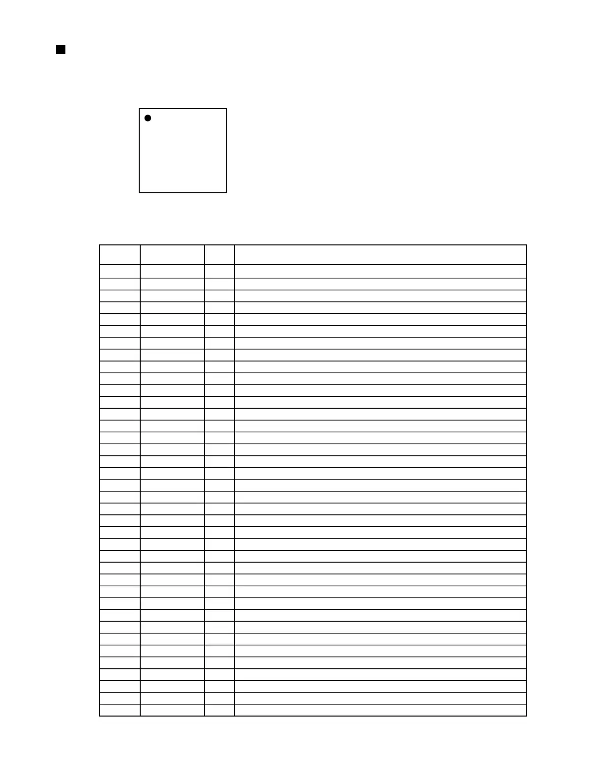
MN101C12G (IC701) : System micom
1
25
~
75
51
~
26 ~ 50
100 ~ 76
Pin No. Symbol I/O Function
1
2
3
4
5
6
7
8
9
10
11
12
13
14
15
16
17
18
19
20
21
22
23
24
25
26
27
28
29
30
31
32
33
34
35
36
37
38
GND
CS0
CS1
CS2
NTSEL
POWER SW
SHUT1
KEY1-5
KEY6-10
VREF
VDD
OSC2
OSC1
VSS
-
-
MMOD
OSDCS3
RSTE
OSDDO
S2UDT
U2SDT
SCLK
BUSY
CPURST
REQ
REMO
CS3
TEST
TEST
TEST
NC
RESET
NC
NC
VDD
OSDCK
NT
GND
A set bit0 (It is effective in the U.E version)
A set bit1 (It is effective in the U.E version)
A set bit2 (It is effective in the U.E version)
NTSC/PAL switch SW input
Power key input
JOG shuttle input (AD)
10 Key input (1~5)
10 Key input (6~10, +10)
+B (Apply 5V)
+B (Apply 5V)
10MHz OSC
10MHz OSC
GND
Unused, Connects with GND
Unused
Connects with GND
V.ENCODER chip selection
V.ENCODER reset
V.ENCODER communication DATA
Communication between unit microcomputers DATA OUT
Communication between unit microcomputers DATA IN
Communication between unit microcomputers CLK
Communication between unit microcomputers BUSY
Unit microcomputer reset
Communication between unit microcomputers REQ
Remote control interruption
Set password change judgment bit(H:Change, L:Usual)
Un used
H:Checkers mode, L:Normal mode
H:Running mode, L:Normal mode
Un used
Reset input
Un uesd
Un used
Un used
V.ENCODER communication CK
NTSC/PAL Switching
-
I
I
I
I
I
I
I
I
-
-
O
I
-
I
O
I
O
O
O
O
I
O
O
O
I
I
I
I
I
I
I
I
O
O
-
O
O
1.Terminal layout
2.Pin function
 Loading...