XV-N50BK,XV-N55SL
1-18 (No.A0041)
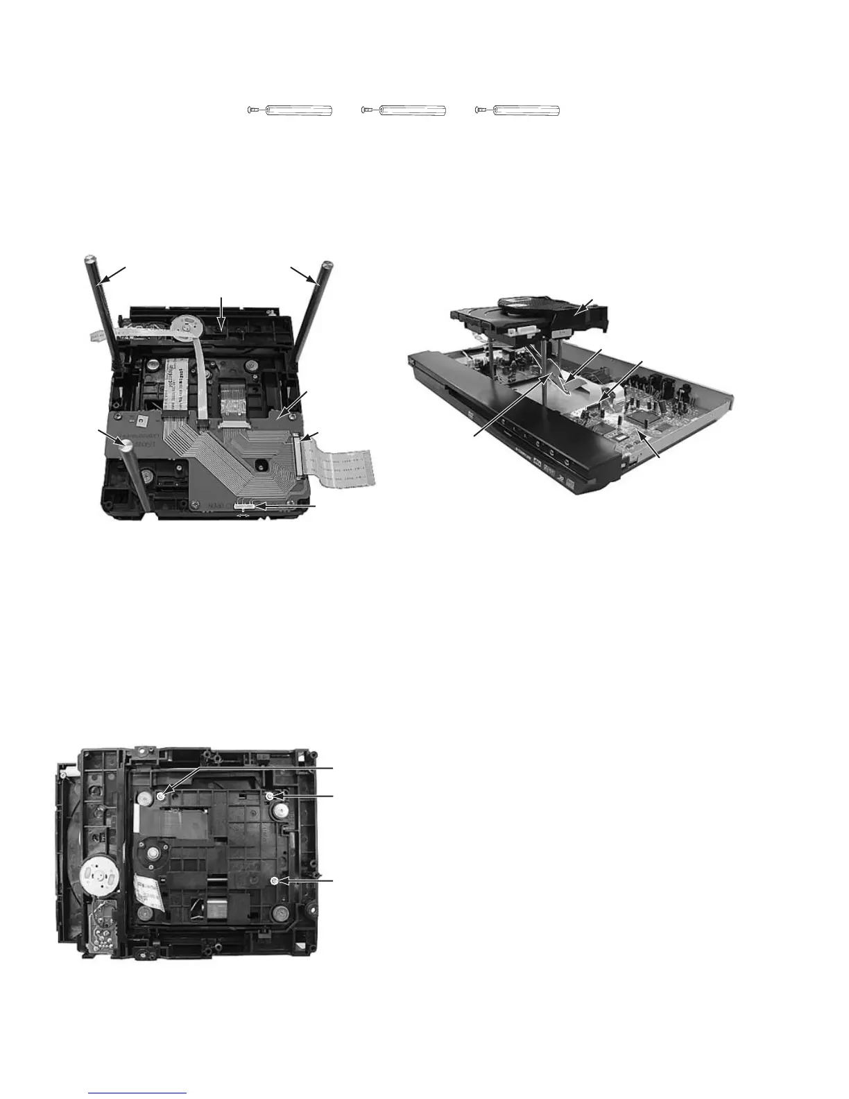
3.7.1 Tool for adjustment
*Stud: One set (four studs), Part number: JIGXVS40 (Note: One of the four studs is not used here.)
3.7.2 Preparation for adjustment
(1) See the disassembly procedure, and remove the Mechanism assembly from the main body.
(2) Remove the relay board attached to the mechanism assembly.
(If you disconnect the wires connected to the Relay board, connect them again.)
(3) Attach the three studs to the Mechanism assembly.
(4) Put the Mechanism assembly in the center of the main body, and connect the 50 pin wire from the connector CN4 on the
Relay board to the connector CN101 on the Servo control & signal output terminal board.
3.7.3 Adjustment
(1) Set the unit to test mode.
(2) Press the "CHOICE" key of the remote controller three times, and the FL display is displayed "CHECK".
(3) Insert a test disc (VT-501), and press the numeric key "1" of the remote controller for automatic adjustment.
(4) After a few seconds, press the numeric key "6" of the remote controller. Then, the FL display displays a jitter value.
(5) Turn the adjustment screws on the underside of the traverse mechanism with phillips screw driver until the maximum jitter value
is displayed on the FL display. (In this model, a bigger jitter value means a better result.)
NOTE:
During operation, the switch on the Relay board should be switched to "OPEN".
Reference values to judge whether the jitter is allowable or not are displayed, instead of actual jitter values.
POINT:
Turn the adjustment screws a and b to the same angle in the
right direction. And turn the adjustment screws a and b to the
same angle in the left direction. Then, turn the screws a and b
in either the right or the left direction to increase the number of
jitter. Don't turn the adjustment screw c.
Stud

 Loading...


