XV-S40BK/XV-S42SL/XV-S45GD
XV-S30BK/XV-E100SL
1-28
1
2
3
4
5
6
7
8
9
10
11
12
13
14
15
16
17
18
19
20
21
22
23
24
25
26
27
28
29
30
-
O
-
O
-
-
O
-
I
I
I
I
I
I
I
-
-
I
-
-
I
I
O
O
-
O
-
O
-
-
Pin No.
Symbol
NC
A3
NC
A2
NC
NC
A1
GND
H1+
H1-
H2+
H2-
H3+
H3-
VH
BR
CNF
SB
FG2
FR
ECR
EC
PS
FG
VCC
GSW
VM
RNF
I/O Description
3.Pin function
Non connect
Output 3 for spindle motor
Non connect
Output 2 for spindle motor
Non connect
Non connect
Output 1 for spindle motor
Connect to ground
Positive input for hall input AMP 1
Negative input for hall input AMP 2
Positive input for hall input AMP 2
Negative input for hall input AMP 2
Positive input for hall input AMP 3
Negative input for hall input AMP 3
Hall bias terminal
Non connect
Capacitor connection pin for phase compensation
Short brake terminal
Non connect
Non connect
Torque control standard voltage input terminal
Torque control voltage input terminal
Start/stop switch (power save terminal)
FG signal output terminal
Power supply for signal division
Gain switch
Power supply for driver division
Resistance connection pin for output current sense
Connect to ground
Connect to ground
BA6664FM-X
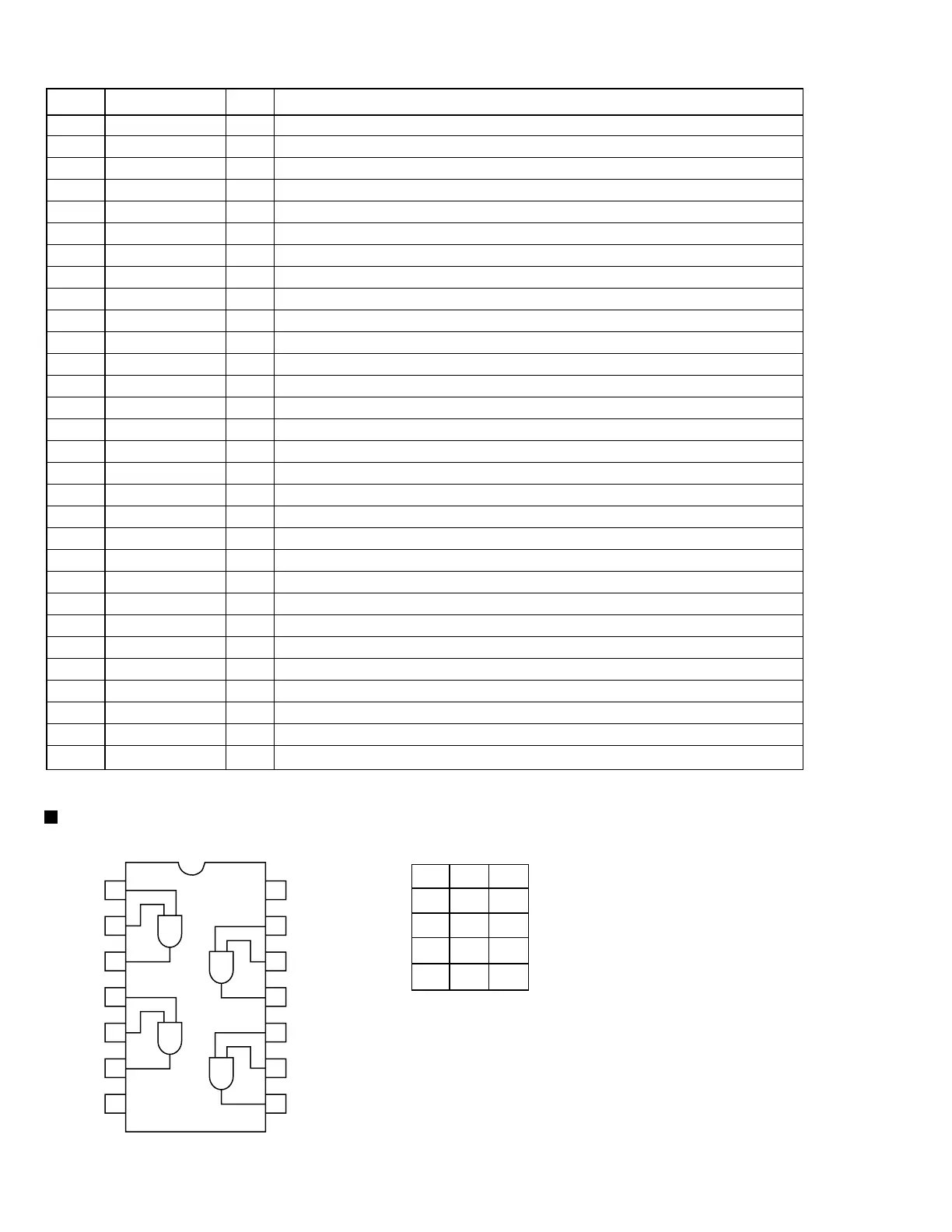
74VHC08SJ-X(IC411) / 74VHCT08ASJ-X(IC412):2-input AND gate
1.Pin layout 2.Truth table
1
2
3
4
5
6
7
14
13
12
11
10
9
8
VCC
4G
4A
4Y
3G
3A
3Y
1G
1A
1Y
2G
2A
2Y
GND
G
L
L
H
H
Y
Z
Z
Z
L
A
L
H
L
H
 Loading...