13 2
INTRODUCTION
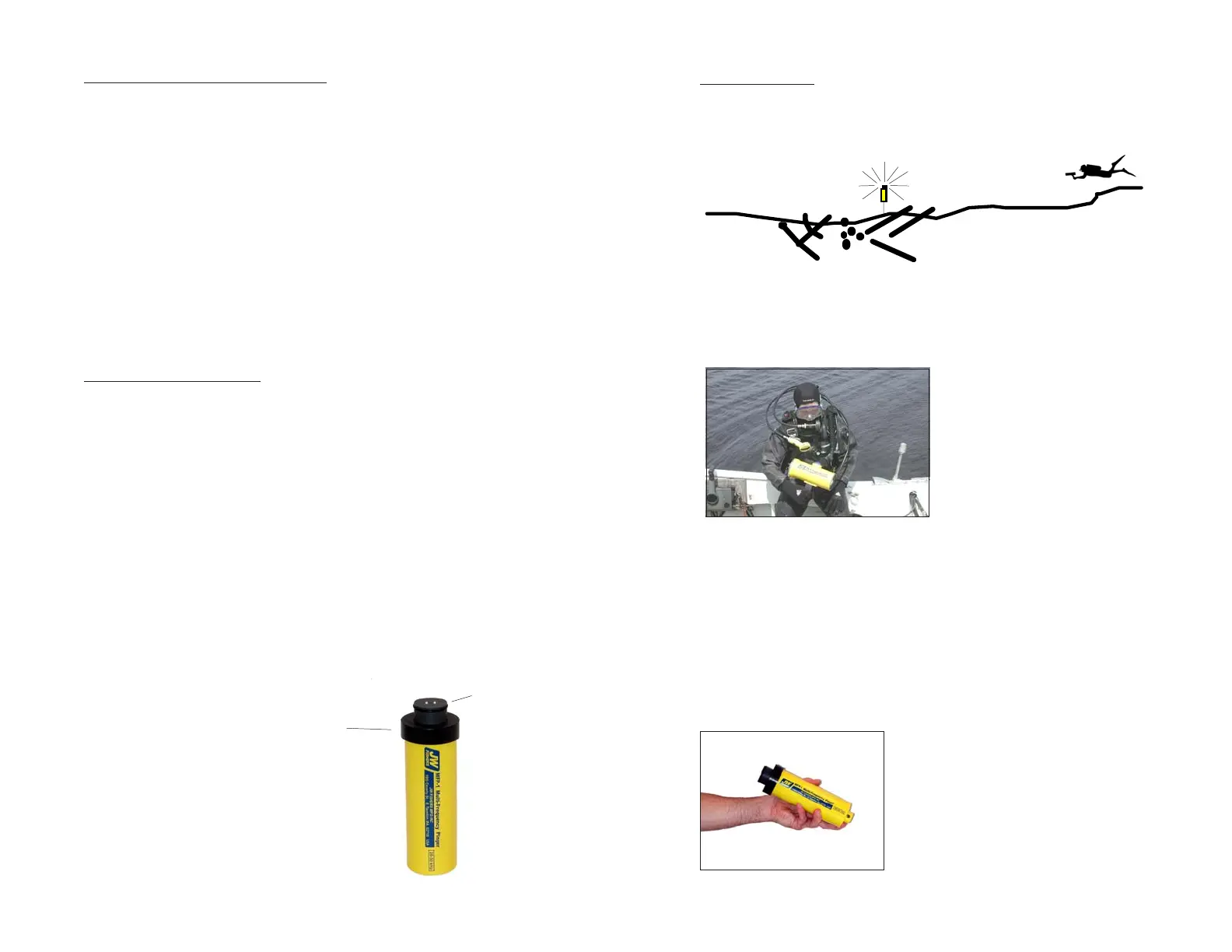
Pingers are devices that generate acoustic signals underwater.
They are used to mark an underwater site or piece of equipment so
a returning diver, using a pinger receiver, can locate the exact spot.
DIVER WITH PINGER RE-
CEIVER PREPARING TO DIVE
TO LOCATE PINGER IN WATER.
JW Fishers family of commercial grade pingers include both the
Single Frequency Pinger (SFP-1) and the Multifrequency Pinger
(MFP-1). The SFP-1 is available in several frequencies one of
which is specified at time of order (22, 32, 40, or 50kHz). The MFP-
1 has user selectable frequencies from 20 to 50 kHz in 500 Hz
increments. The operator selects one of 60 different frequencies
before deploying the pinger. Many pingers can be deployed in the
same general area, each transmitting at a different frequency. This
enables a diver with a pinger receiver to pinpoint the exact location
of each pinger without interference from the other pingers.
THE SFP-1 AND MFP-1 ARE
THE SAME SIZE.
Pingers are available with different transmit frequencies so sev-
eral can be deployed in the same general area without interference
from each other. The diver adjusts his pinger receiver to the fre-
quency of the desired pinger and the receiver leads him to it.
ELECTRONICS BOARD REMOVAL
The electronics board is bolted to the transducer. The transducer is
held in place by the Retaining Cap. Open the pinger housing by first
turning the Retaining Cap counterclockwise (it should not be tight.)
When the Retaining Cap is loose, pull out on the Retaining Cap and
transducer which will remove the transducer and electronics board
from the housing.
Note that the transducer has an o-ring (below the Retaining Cap)
that seals the pinger from water. Be careful to keep this o-ring clean
and free of damage. The o-ring can be lubricated with a silicon based
lubricant.
When reinstalling the electronics be sure the o-ring is pushed into
the pinger housing. To do this, push the end of the black transducer
in the direction of the housing. Screw the Retaining Cap snug, but
do not overtighten.
BATTERY INSTALLATION
The SFP-1 and the MFP-1 use two 9 volt Alkaline or Lithium bat-
teries. The “Extended Operations Option” package uses six batter-
ies.
To install batteries:
1) Remove the electronics board (see above.)
2) The batteries are mounted directly on the electronics board;
one battery on each side of the board ( the “Extended Operations
Option” package uses three batteries on each side.) The batteries
are installed “terminal end” in first (observe correct polarity.)
3) After the battery terminals are pushed in-place, push down on
the other end of the battery while pushing away the black tubing to
make room for the battery. It is intended to be a tight fit. The black
tubing holds the battery in-place so it cannot be jarred loose.
The black tubing is not used for the bottom battery on the back
side of the board. This battery is held in-place by the sponge rub-
ber in the bottom of the housing.
Retaining Cap
(o-ring under cap)
Transducer

 Loading...