9 6
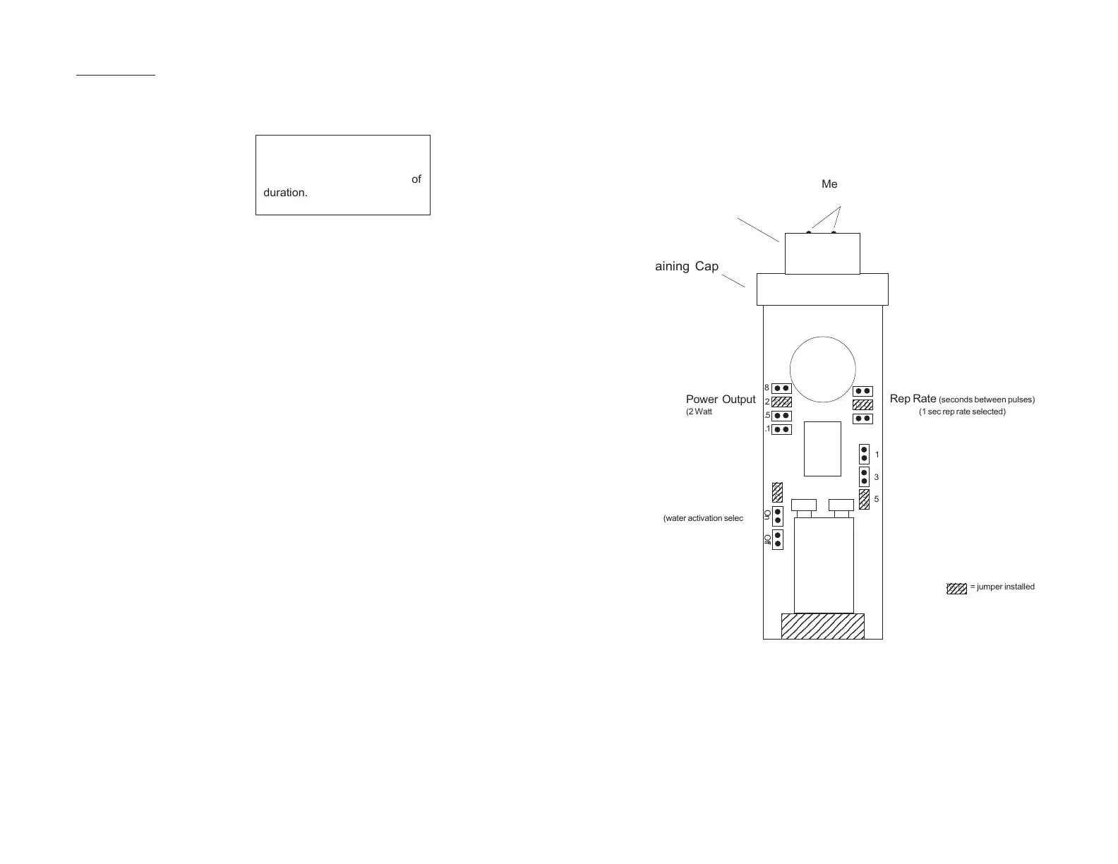
Single Frequency Pinger Jumper Layout
(Front side of board shown)
OPERATION
Pinger operation is simple and straight forward.
1) Remove the electronics board (see page 11).
2) Install “push on” jumpers (see page 6 or 7) for:
• Power Output ............................................................ 2 watt
• Rep Rate .................................................................. 1 Sec
• Pulse Length ............................................................. 3 ms
• Power Activation............................................................ On
Always test pingers and pinger receivers on land or in shallow
water before deploying in open water. Pingers do not transmit sig-
nals very far through the air; however, they can be detected 5 to 10
feet away by a pinger receiver.
If you are operating the pinger in air, a “clicking sound” can be
heard from the transducer each time a “ping” occurs. You may not be
able to hear it if you have the jumpers set for a low power output.
Before deploying a pinger in the water be sure the electronics and
seals are pushed into the pinger housing. To do this, push the end of
the black transducer in the direction of the housing. Screw the Re-
taining Cap snug, but do not overtighten.
Be sure to use fresh batteries each time the pinger is used. The
cost of a fresh set of batteries is small compared to the loss of a
“dead” pinger, or a delay in the project while you relocate the target.
Pulse Length
(5 ms selected)
234
8
2
.5
.1
Power Output
(2 Watt selected)
Battery
#1
234
2
.5
1
2
2
2
Water
Power Activation
(water activation selected)
On Off
2345678901
2345678901
234
= jumper installed
Metal Contacts
(for Water power activation)
Transducer
Retaining Cap
1
5
2
2
2
2
3
Rep Rate (seconds between pulses)
(1 sec rep rate selected)
Sample settings shown are for
moderate distances (less than
200m) and less than a week of
duration.
 Loading...