Instruction Manual
Section Three
from the hydraulic system. Valve No. 18 pictured on the Hydraulic Pump and Tank
Assembly, shown in Photo 5, is used to regulate the flow of oil and has been pro-
perly set at the factory for the correct grade of oil at normal operating temperature.
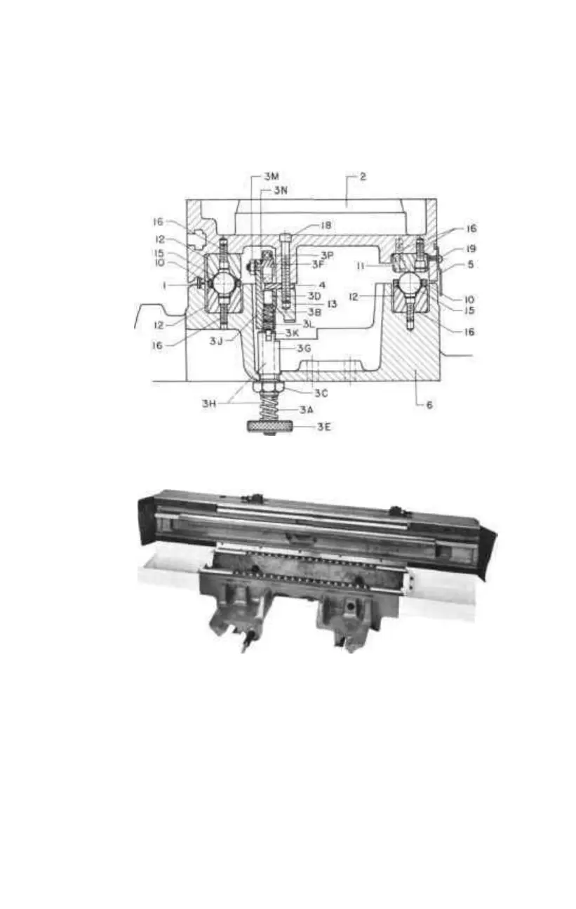
BALL-TRACK TABLE/SADDLE END VIEW
PHOTO OF TOP OF BALL-TRACK SADDLE
III. BALL-TRACK HYDRAULICALLY POWERED MACHINES OR
MACHINES WITH PRESSURE LUBRICATION SYSTEM
These models have special piping to the center of the "V"-ways, and receive
regular amounts of oil or way lube from the hydraulic system or power way lube
system. Periodic inspection is advisable and may be done in the following manner.
It is necessary to disengage the piston rod from the table at the right end of the
table. Remove the thumb nut, move the table slightly further to the right, and
remove the collar from the piston rod (reach under the table end to locate on
rod! Move the table to the extreme right until the saddle table way reservoirs
—2--
A
B.