Instruction Manual
Section Five
the steps in set-up procedure given in parts I, II, and III for primary
clearance. Match the secondary clearance angles on the cutter or use
the suggested clearance from table V, on page 107. The toothrest may
have to be adjusted, the workhead tilted one way or the other farther
(IN THE VERTICAL PLANE), or, when the machines have a tilting wheel-
head, the Wheelhead tilted farther than the primary angle setting. Suffi-
cient grinding is accomplished in order to reduce the primary land to about
1
/
16
or
1
/
32
inch in width
C. Grinding Procedure:
The process duplicates that given in parts I and II for the face and chamfer
clearance lands, except as noted in B-1 above.
CHAPTER 9
Form Relieved Cutters
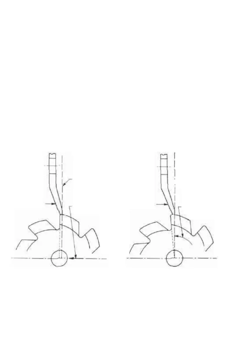
Form relieved cutters are sharpened by grinding the teeth faces as pictured in
Photos 37, 38, 39, 40, 41, 42 Figure 37A shows the correct and incorrect way to
GRINDING
WHEEL
LINE PARALLEL TO RADIUS
ON WHICH TOOTH IS
INCORRECTLY GROUND
LINE OF ADJUSTMENT
OF WORK TO
GRINDING WHEEL
GRINDING
WHEEL
RADIUS ON WHICH
TOOTH IS
CORRECTLY GROUND
LINE OF ADJUSTMENT
OF WORK TO
GRINDING WHEEL
WRONG
Figure 37A
RIGHT
sharpen these cutters. On K. 0. Lee grinders, the usual method of grinding these
cutters is to place them between centers, sharpening them with a saucer wheel.
Certain formed cutters, such as Fellows gear shaper cutters, are sharpened by
rotating them in with a motorized workhead. This process is described at the end
of the chapter. New form relieved cutters should have the backs of the teeth ground
prior to using these surfaces for indexing with a toothrest. This is done for the pur-
pose of creating indexing points on the cutter teeth which are equally distant from
the center of the cutter as well as to provide teeth backs which are parallel with any
axial helix that may exist on long cutters. From the foregoing, it can be seen that
—48—