Instruction Manual Section Five
STAGGERED TOOTH MILLING CUTTERS (SEE PACE 41 FOR ILLUSTRA-
TION AND DESCRIPTION OF A TYPICAL SET-UP.)
Staggered tooth milling cutters, having alternately
right and left-hand spiral teeth may be sharpened at
one setup by using a toothrest with the top of the
blade either rounded or shaped with a double angle
(INVERTED V). The operation is similar to grinding
a plain spiral mill, with the cutter mounted on an
arbor between centers and the toothrest fastened to
the Wheelhead. Relief may be generated directly by
tilting the Wheelhead as in lll-C above.
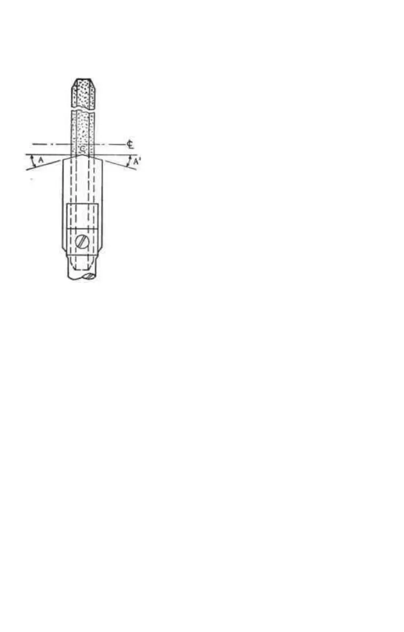
The blade of the special toothrest shown in Figure 17
is ground to coincide with the right and left spiral
angles of the cutter teeth. The high point (c) of the
toothrest must be located in the center of the cutting
edge (FACE) of the wheel. The Wheelhead is raised
sufficiently to give the desired relief.
The cutter is traversed across the wheel with the
spiral edge of the tooth resting on the correspond-
ing edge of the toothrest. In grinding the next tooth,
having the alternate spiral, the cutter is traversed in
the opposite direction, using the other edge of the
toothrest. Best results will be obtained if the face of
either the straight wheel or cup wheel is beveled to
about ⅛ inch wide at the periphery, or the cutting
edge.
SIDE MILLING CUTTERS (SEE PAGE 40 FOR ILLUSTRATION AND
DESCRIPTION OF A TYPICAL SET-UP.)
The cutter is mounted on a stub arbor and locked into the self-locking
taper in the universal workhead. The cutter may also be mounted on a
straight arbor and held between centers. The toothrest is usually fastened
to the workhead or table.
While the setup illustrated shows the use of a cup wheel and tilting wheel-
head, a straight wheel can also be used, in which case the cutter arbor is
set in a horizontal position and the Wheelhead raised, or lowered, to pro-
duce the required side tooth relief The peripheral teeth of side milling
cutters are sharpened in exactly the same manner as previously described
for plain cutters. If the cutter is helical, the toothrest assembly is mounted
on the Wheelhead.
FACE MILLING CUTTERS (SEE PAGE 43 FOR ILLUSTRATION AND
DESCRIPTION OF A SPECIFIC SET-UP.)
Special machines of suitably heavy construction are available for sharpening
large face milling cutters. However, if they are not too large, they can be
sharpened on a universal tool and cutter grinder. They should be mounted
on a tapered shank supported in the workhead spindle in the same manner
as they are supported on the milling machine. The operations involved in
sharpening a face milling cutter are similar to those in sharpening a shell
end mill and include grinding the periphery, face, and corners of the blades.
For cast iron, the peripheral relief angle should be about 4 degrees; for soft
steel, about 6 degrees A secondary clearance may be ground to leave a
land
1
/
16
inch to
3
/
32
inch wide.
Figure 17—Shape of blade
of tooth rest for sharpening
staggered tooth milling
cutters.
—27—