Instruction Manual Section Five
B. Toothrest and Clearance Angle Settings:
1. Non-tilthead grinders: Prior to setting the toothrest, adjust the workhead
upward to the necessary primary clearance angle. The base of the uni-
versal toothrest may be clamped on top of the workhead or on the top of
the swivel table, depending on the size of the cutter and the position of
its blades. The position recommended for ease of set-up, as shown in
Photo 32, is with the toothrest blade pointed down onto a cutter blade
face which is facing up at the point of contact for grinding the relief.
Using the height gauge, adjust the toothrest blade onto the face of one
blade so that the blade is at the approximate center of the wheel and the
periphery of the cutter face is at the same height as the center of the
cutter. Use the micrometer with spring-loaded blade as shown in the
photo and adjust it to hold the cutter from rotating up at the point of
grinding, and so that it will not be touched by the wheel. The toothrest
blade must be free to spring aside when the mill is rotated in order to
bring the next blade into grinding position. Under same conditions, it
may be possible to set the toothrest from below the wheel, as shown in
Photo 33 (photo shows periphery being sharpened.). (Page 20 shows below
center toothrest location.)
PHOTO 34
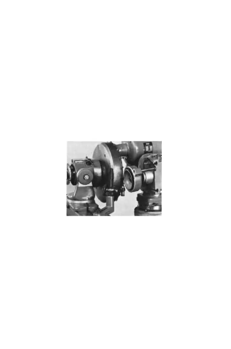
2. Tilthead Grinders: Mount the universal toothrest base on the table as
shown in Photo 34, and then position the toothrest blade to the approxi-
mate center of the wheel at the wheel edge (EITHER SIDE DEPEND-
ING ON CUTTER ROTATION AND SET-UP) so that it will not touch
the wheel. Care must be taken to see that the toothrest will allow other
blades of the cutter to clear the wheel during the sharpening process.
Center the cutter blade edge to be ground with the cutter center, as
described in B-1 above. Loosen the swivel Wheelhead bracket screws,
tilt the Wheelhead to the desired primary clearance angle, and tighten.
3. If the cutter has teeth with significant radial rake, mount the toothrest
on the Wheelhead. Modify steps 1 and 2 above accordingly.
C. Grinding Procedure:
1. Engage the table transmission to the greatest reduction and traverse the
table to the left (or right) to a point where a blade cutter face will pass
beyond the wheel edge toward the center of the wheel. Set a stop at the
right (or left) end of the table to limit further travel in this direction.
--45--