Instruction Manual
Section Five
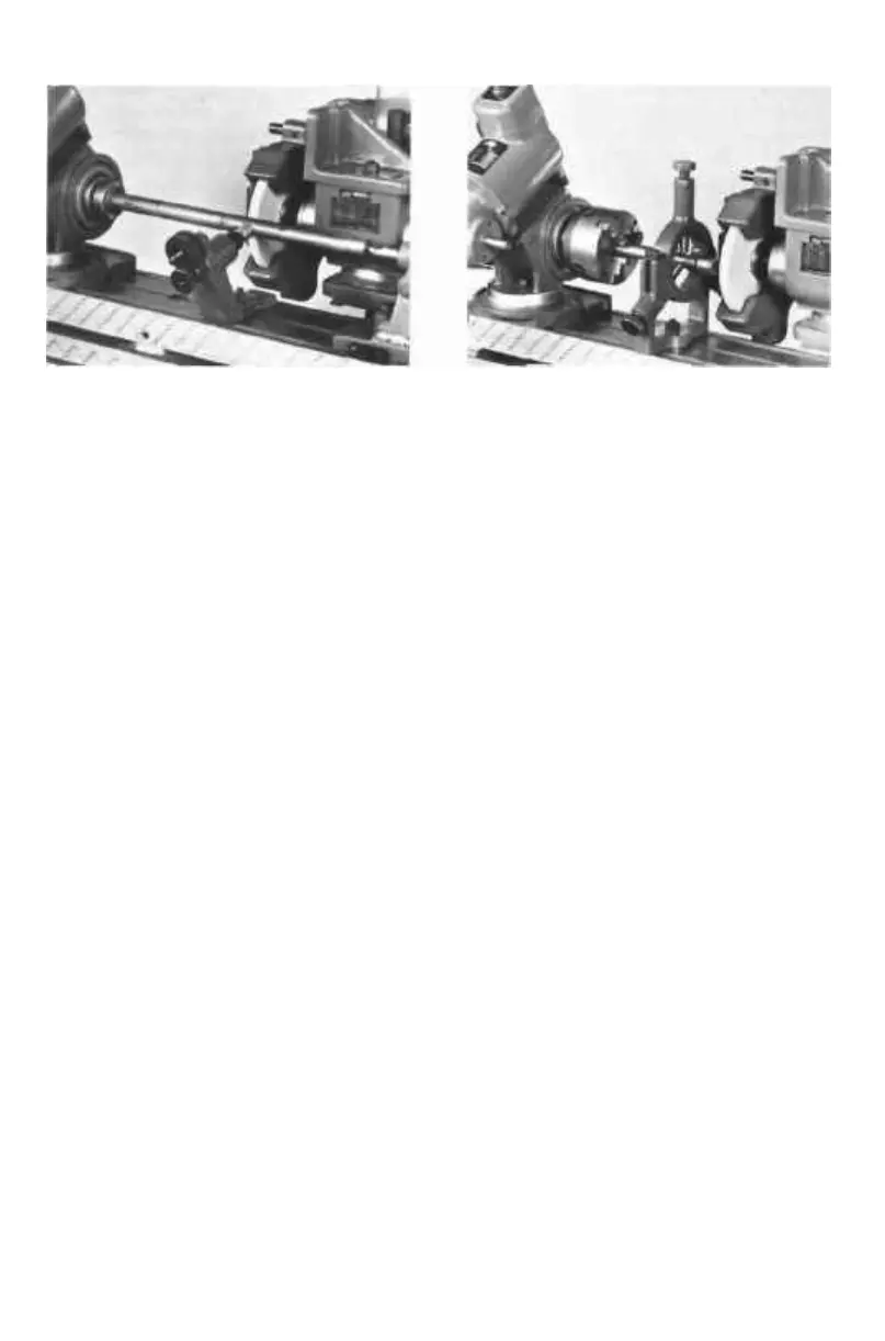
PHOTO 60 PHOTO 61
L Special Steady Rests:
I. To aid in the support of the work against the grinding wheel pressure
which forces the work down and away from the wheel, one or more
steady rests should be employed when grinding long, relatively thin pieces.
Care must be taken not to force the work into the wheel, as such forcing
will cause the work to be ground to a smaller size in the area of the
steady rest than at other places
2. Special steady rests, such as the BA969 Follow Rest or BA938 Steady Rest
(Photos 60 and 61), are available for K. 0. Lee Grinders.
M. If grinding in recessed areas with the wheel on the left end of the spindle
proves difficult due to Wheelhead swivel interference, mount the wheel on the
right end of the spindle as shown in Photo 59 and explained in l-C above.
II. INTERNAL CYLINDRICAL GRINDING
This type of cylindrical grinding is used to finish holes in cutters, bushings, gauges,
and other machine parts. Holes may be straight, tapered, or formed relative to
the axis of the work With the exception of honing, internal grinding is the most
accurate method of furnishing holes to size. The universal tool and cutter type of
machine provides internal grinding capacities that will handle most requirements
for the average shop or toolroom The general method of producing the grinding
action is similar to that of O. D. cylindrical operations.
On many K. O. Lee grinders, the standard spindle on the machine is capable of
holding I. D. wheel-holding arbors and can achieve the necessary high R.P.M. to
obtain the correct surface feet per minute The machine wheel speed plate will
usually indicate whether the machine's spindle is of this type. If the machine
has only a heavy-duty spindle, an additional spindle (QUILL ASSEMBLY) must be
obtained to accomplish I.D. work. Consult Section Four, Part III, Pages 13, 17 for
instruction on the attachment of internal grinding wheel-holding arbors onto the
spindle. The functioning of the motorized workhead is described in Section Four,
Part III, Page 18, and also in this chapter, Part I. It will often be used with the
three-jaw universal chuck (LOCKED INTO THE SPINDLE TAPER, SEE PHOTO 62),
which is capable of holding most work pieces. Small bushings can also be held in
the workhead with the aid of a collet fixture and spring collet. Consult Figure 62A
of this chapter for dimensions of I.D. arbors and approximate I.D. grinding hole
size and depth.
—78-
 Loading...