The K-Rain 2000 Series Single Station Controller is an irrigation timer designed for automatic and manual operation of a single zone valve. This instruction manual provides comprehensive details on its functions, setup, wiring, and troubleshooting.
Function Description:
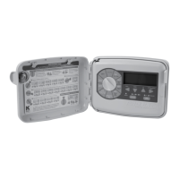
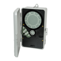
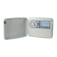
The controller is primarily used to automate irrigation schedules. It features a 24-hour time dial for setting operating times and a 14-day day wheel for programming specific days of operation over a two-week period. An Auto-Off-On switch knob allows users to select between manual operation (ON), automatic operation (AUTO), or to stop all functions (OFF). The device is housed in an enclosure, with chassis screws securing the internal components. An electrical connection strip facilitates input and output wiring.
Important Technical Specifications:
While specific voltage and current ratings are not explicitly listed for the controller itself, the manual provides details for various models and associated components:
- Motors:
- 110 VAC motor, 60 cycle (Part No. 1111025)
- 220 VAC motor, 60 cycle (Part No. 1122025)
- Timing Pins:
- 15 minute white timing pins (18 included) (Part No. 1009955)
- 7 minute yellow timing pins (18 available) (Part No. 1009956)
- 3 minute orange timing pins (18 available) (Part No. 1009957)
- Mixed assortment of timing pins (6 each available) (Part No. 1009947)
- 15 hour black timing pins (6 available) (Part No. 1009959)
- Relays:
- Relay, 110 VAC, 60 Hz coil, double throw, single pole, 2 HP (Part No. 1320110)
- Relay, 220 VAC, 60 Hz coil, double throw, single pole, 2 HP (Part No. 1320220)
- Transformers:
- Transformer, 110 VAC input, 24 VAC, 30 VA output (Part No. 1211027)
- Transformer, 220 VAC input, 24 VAC, 30 VA output (Part No. 1222024)
- Pilot Valve:
- Pilot Valve for model 2116 (w/o solenoid) (Part No. 1003042)
The controller models covered in the wiring diagrams include:
- Model 2110
- Model 2116
- Models: 2112, 2120 & 2210
- Models: 2114, 2124, 2214
Usage Features:
- Time Dial: Rotates clockwise once every 24 hours. Automatic operation is programmed by inserting timing pins into the dial holes. The correct time of day is indicated when the "TIME" arrow aligns with the time on the dial.
- Day Wheel and Retained Pin Assembly: Features 14 pin locations for a two-week program. The controller operates automatically only on days where the corresponding day wheel pin is depressed. The "DAY" arrow indicates the current day.
- Auto-Off-On Switch Knob:
- ON: For manual operation.
- AUTO: For automatic operation based on programmed times and days.
- OFF: Stops both manual and automatic functions.
- Setting Day and Time: To set the day, turn the Day Wheel until the correct day aligns with the "DAY" arrow. To set the time, turn the Time Dial CLOCKWISE until the correct time aligns with the "TIME" arrow. Caution: The time dial must only be turned clockwise; forcing it in reverse can cause damage.
- Manual Operation: Turn the Auto-Off-On switch to "ON." Turn it back to "OFF" when manual operation is no longer needed.
- Daily Operation Programming: For desired operating days, push the day wheel pin down fully. For days when operation is not desired, gently pull the day pin out.
- Operating Times Programming: The 24-hour Time Dial has 96 15-minute increments. White 15-minute timing pins are provided. Longer timing periods can be achieved by placing multiple white pins next to each other. Shorter duration pins (7-minute yellow and 4-minute orange) are also available separately.
- Multiple Zone Valve Operation: When operating a multiple zone valve, ensure at least one pin space is left between groups of pins representing different zones on the Time Dial.
- Starting Automatic Operation: After setting the correct time, day, and desired operating times, turn the Auto-Off-On switch knob to "AUTO."
Maintenance Features:
-
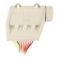
Electrical Connection Strip: Allows for input and output electrical connections. Users should consult the Electrical Circuit and Connection Diagram before wiring.
-
Troubleshooting Guide: The manual includes a detailed troubleshooting section for common issues:
- Controller fails to keep proper time:
- Cause: No power or improper voltage to motor.
- Solution: Check electrical connections and voltage supply (120 or 240 volts as specified).
- Cause: Clock motor running but time dial not turning (broken drive gear).
- Solution: Remove time dial, inspect/replace drive gear, and ensure free clockwise rotation.
- Controller improperly staying ON:
- Cause: Switch being activated (wires pushing against switch/relay, or pulled out wires).
- Solution: Ensure wires are clear of the switch/relay and properly connected.
- Cause: Controller improperly wired.
- Solution: Check wiring diagram to ensure input wires are not directly wired to the load.
- Cause: Switch adjustment needed for proper automatic operation.
- Solution: Adjust the switch point using the adjustment screw on the switch cover. Tighten clockwise for earlier activation, counter-clockwise for later activation. A clicking sound should be heard when the switch arm is pulled back halfway between the time dial edge and the timing pin's far edge.
- Cause: Switch knob not in OFF position.
- Solution: Turn Auto-Off-On knob to OFF.
- Controller does not turn ON in manual mode:
- Cause: No power to controller.
- Solution: Verify proper wiring according to the diagram and check the circuit breaker.
- Controller fails to operate properly in automatic (AUTO) mode:
- Cause: Day Wheel not properly programmed.
- Solution: Review programming instructions for the day wheel.
- Cause: Auto-Off-On knob not set properly.
- Solution: Turn the knob to AUTO.
- Cause: Switch contacts or relay worn out.
- Solution: Replace the switch or relay (refer to parts list) and ensure proper rewiring. A nut driver tool is recommended for removing black retainer nuts.
-
Warranty: K-Rain® products come with a "Limited Warranty" for two years from the date of purchase, covering defects in workmanship or material. The warranty does not cover damage from misuse, neglect, abuse, normal wear and tear, accident, exterior appearance, color, or improper installation. It applies only to the original user. For defects, contact a K-Rain® installer, distributor, or K-Rain® Manufacturing Corporation. Repairs or replacements may take up to 4 weeks. Replaced products are covered for the remainder of the original warranty period.
Safety Precautions (Electrical Connection Instructions):
- CAUTION: Disconnect power to the controller prior to installation or service.
- Ensure the proper controller is selected for the application.
- Use appropriate gauge wire and ensure all wiring meets local codes.
- Avoid excessive pulling on controller wires to prevent disconnection.
- Properly ground the controller.
- When reinstalling the controller face or lower cover, ensure wires are not trapped between standoffs and screws.
- Remove the lower cover on the controller face before making wire connections.
- Make wire connections to the electrical connection strip as indicated by the Electrical Circuit and Connection Diagram.
- Reinstall the lower cover on the controller face after wiring.