STANDARD NOZZLE PERFORMANCE
METRIC
Pressure Radius Flow
KPa Bars Meters L/M M
3
/H
206 2.111.07.6 0.45
275 2.811.69.1 0.55
344 3.412.210.2 0.61
413 4.112.2 11.0 0.66
206 2.18.5 1.9 0.11
275 2.88.8 2.3 0.14
344 3.48.8 2.7 0.16
413 4.19.1 3.0 0.18
206 2.18.8 2.6 0.16
275 2.89.1 3.0 0.18
344 3.49.1 3.4 0.20
413 4.19.4 3.8 0.23
206 2.19.1 3.4 0.20
275 2.89.4 3.8 0.23
344 3.49.4 4.5 0.27
413 4.19.8 4.9 0.30
206 2.19.8 4.5 0.27
275 2.810.15.3 0.32
344 3.410.46.1 0.36
413 4.110.46.8 0.41
206 2.111.09.8 0.59
275 2.812.211.4 0.68
344 3.412.812.9 0.77
413 4.112.814.0 0.84
206 2.111.615.9 0.91
275 2.813.118.5 1.11
344 3.414.020.8 1.25
413 4.114.3 22.7 1.36
275 2.813.722.7 1.36
344 3.414.625.7 1.54
413 4.114.928.8 1.73
482 4.815.531.0 1.86
U.S.
Nozzle Pressure Radius Flow
PSI Ft. GPM
#3 30 36' 2.0
40 38' 2.4
50 40' 2.7
60 40' 2.9
#0.5 30 28' 0.5
40 29' 0.6
50 29' 0.7
60 30' 0.8
#0.75 30 29' 0.7
40 30' 0.8
50 30' 0.9
60 31' 1.0
#1 30 30' 0.9
40 31' 1.0
50 31' 1.2
60 32' 1.3
#2 30 32' 1.2
40 33' 1.4
50 34' 1.6
60 34' 1.8
#4 30 36' 2.6
40 40' 3.0
50 42' 3.4
60 42' 3.7
#6 30 38' 4.2
40 43' 4.9
50 46' 5.5
60 47' 6.0
#8 40 45' 6.0
50 48' 6.8
60 49' 7.6
70 51' 8.2
Data represents test results in zero wind for the RPS50 Rotor. Adjust for local conditions.
Radius may be reduced with nozzle retention screw.
LOWANGLE NOZZLE PERFORMANCE
METRIC
Pressure Radius Flow
KPa Bars Meters L/M M
3
/H
207 2.0 6.7 4.5 .34
275
3.07.3 6.4 .39
344 3.57.9 6.8 .41
413 4.08.5 7.6 .46
207 2.08.8 11.4 .68
275 3.0 9.8 11.7 .71
344 3.5 10.7 13.2 .80
413 4.0 11.3 14.4 .87
207 2.0 9.4 12.9 .78
275 3.0 10.4 14.8 .89
344 3.5 11.3 16.7 1.00
413 4.0 11.6 17.8 1.07
275 3.0 11.6 24.6 1.68
344 3.5 12.2 27.6 1.66
413 4.0 12.8 30.3 1.82
482 5.0 13.4 32.6 1.96
U.S.
Nozzle Pressure Radius Flow
PSIFt. GPM
#1 30 22' 1.2
40 24' 1.7
50 26' 1.8
60 28' 2.0
#3 30 29' 3.0
40 32' 3.1
50 35' 3.5
60 37' 3.8
#4 30 31' 3.4
40 34' 3.9
50 37' 4.4
60 38' 4.7
#6 40 38' 6.5
50 40' 7.3
60 42' 8.0
70 44' 8.6
Right
Start
Left
Stop
REMOVING THE NOZZLE RETENTION SCREW
Use the Key (A) to remove the nozzle retention screw (B) by turning
counter-clockwise to remove or clockwise to re-install.
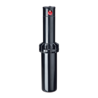
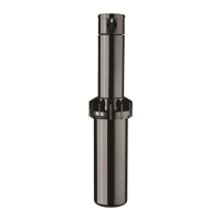
PULL UP THE RISER
Insert the Key (A) in the keyhole (C) on the top of the nozzle turret (D)
and turn the key 1/4 turn to insure that the key does not slip out of the
keyhole when you pull it up. Firmly pull up the entire spring-loaded riser
to access the nozzle socket (E). Hold the riser assembly with one hand.
REMOVING THE NOZZLE
With nozzle retention screw removed, the nozzle may be removed by
either turning on the water (wear safety glasses when using this method),
or by pulling outward on nozzle wing (F) with a pair of needle-nose pliers.
INSTALLING A NOZZLE
Press the desired nozzle (G) into the nozzle socket (E). Make sure the
nozzle number is visible and the nozzle wing (F) are up. Then, re-install
the nozzle retention screw (B). NOTE: The nozzle retention screw is also
a break-up screw and used to adjust the distance of the spray.
NOTE: The RPS50 Gear Driven Sprinkler has
a xed right start and an adjustable left stop.
POSITIONING NOZZLE TURRET TO ITS “RIGHT START”
Place your nger on the top center of the nozzle turret (D). Rotate the
turret counter-clockwise to the left stop to complete any interrupted
rotation cycle. Rotate the nozzle turret clockwise to the right start.
This is the xed side of the arc. The nozzle turret must be held in this
position for arc adjustments. The right start does not change.
ADJUSTING THE RIGHT (FIXED) SIDE OF ARC
If the right side of the arc is not properly aligned, sprinkler may
spray in areas not intended for watering such as driveways or
adjacent properties. The right side arc can easily be realigned.
OPTION 1: REPOSITION CAN ON THE FITTING
Turn the housing can left or right to the desired position.
This may require temporary removal of the soil around the
sprinkler to allow you to grip the sprinkler can.
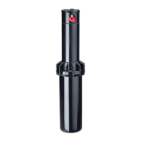
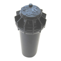
OPTION 2: REMOVE INTERNAL RISER ASSEMBLY AND REPOSITION
Unscrew the top counter-clockwise and remove the internal sprinkler
assembly (J) from the can (K). Once removed with nozzle turret (D) at its
right start, reposition the riser assembly so that nozzle arrow points to
the desired start position. Replace the riser assembly back in the can and
screw on the top. At this point you have realigned the right arc stop, and
you can adjust the left arc to an appropriate setting.
(continued on reverse side)
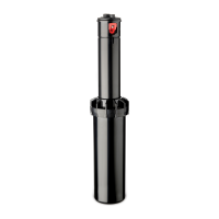
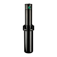
RPS
®
50 Gear Driven Sprinkler Setting Instructions
NOTE: The RPS 50 is factory preset with a 40° arc setting, and includes a pre-installed #1.5 nozzle.
CHANGING A NOZZLE
SETTING THE ARC ADJUSTMENT
1
s
1
s
2
s
2
s
3
s
4
s
STANDARD NOZZLE PERFORMANCE
METRIC
Pressure Radius Flow
KPa Bars Meters L/M M
3
/H
206 2.111.07.6 0.45
275 2.811.69.1 0.55
344 3.412.210.2 0.61
413 4.112.2 11.0 0.66
206 2.18.5 1.9 0.11
275 2.88.8 2.3 0.14
344 3.48.8 2.7 0.16
413 4.19.1 3.0 0.18
206 2.18.8 2.6 0.16
275 2.89.1 3.0 0.18
344 3.49.1 3.4 0.20
413 4.19.4 3.8 0.23
206 2.19.1 3.4 0.20
275 2.89.4 3.8 0.23
344 3.49.4 4.5 0.27
413 4.19.8 4.9 0.30
206 2.19.8 4.5 0.27
275 2.810.15.3 0.32
344 3.410.46.1 0.36
413 4.110.46.8 0.41
206 2.111.09.8 0.59
275 2.812.211.4 0.68
344 3.412.812.9 0.77
413 4.112.814.0 0.84
206 2.111.615.9 0.91
275 2.813.118.5 1.11
344 3.414.020.8 1.25
413 4.114.3 22.7 1.36
275 2.813.722.7 1.36
344 3.414.625.7 1.54
413 4.114.928.8 1.73
482 4.815.531.0 1.86
U.S.
Nozzle Pressure Radius Flow
PSI Ft. GPM
#3 30 36' 2.0
40 38' 2.4
50 40' 2.7
60 40' 2.9
#0.5 30 28' 0.5
40 29' 0.6
50 29' 0.7
60 30' 0.8
#0.75 30 29' 0.7
40 30' 0.8
50 30' 0.9
60 31' 1.0
#1 30 30' 0.9
40 31' 1.0
50 31' 1.2
60 32' 1.3
#2 30 32' 1.2
40 33' 1.4
50 34' 1.6
60 34' 1.8
#4 30 36' 2.6
40 40' 3.0
50 42' 3.4
60 42' 3.7
#6 30 38' 4.2
40 43' 4.9
50 46' 5.5
60 47' 6.0
#8 40 45' 6.0
50 48' 6.8
60 49' 7.6
70 51' 8.2
Data represents test results in zero wind for the RPS50 Rotor. Adjust for local conditions.
Radius may be reduced with nozzle retention screw.
LOWANGLE NOZZLE PERFORMANCE
METRIC
Pressure Radius Flow
KPa Bars Meters L/M M
3
/H
207 2.0 6.7 4.5 .34
275
3.07.3 6.4 .39
344 3.57.9 6.8 .41
413 4.08.5 7.6 .46
207 2.08.8 11.4 .68
275 3.0 9.8 11.7 .71
344 3.5 10.7 13.2 .80
413 4.0 11.3 14.4 .87
207 2.0 9.4 12.9 .78
275 3.0 10.4 14.8 .89
344 3.5 11.3 16.7 1.00
413 4.0 11.6 17.8 1.07
275 3.0 11.6 24.6 1.68
344 3.5 12.2 27.6 1.66
413 4.0 12.8 30.3 1.82
482 5.0 13.4 32.6 1.96
U.S.
Nozzle Pressure Radius Flow
PSIFt. GPM
#1 30 22' 1.2
40 24' 1.7
50 26' 1.8
60 28' 2.0
#3 30 29' 3.0
40 32' 3.1
50 35' 3.5
60 37' 3.8
#4 30 31' 3.4
40 34' 3.9
50 37' 4.4
60 38' 4.7
#6 40 38' 6.5
50 40' 7.3
60 42' 8.0
70 44' 8.6
K
Housing
Can
J
Internal
Sprinkler
Assembly
STANDARD NOZZLE PERFORMANCE
METRIC
Pressure Radius Flow
KPa Bars Meters L/M M
3
/H
206 2.111.07.6 0.45
275 2.811.69.1 0.55
344 3.412.210.2 0.61
413 4.112.2 11.0 0.66
206 2.18.5 1.9 0.11
275 2.88.8 2.3 0.14
344 3.48.8 2.7 0.16
413 4.19.1 3.0 0.18
206 2.18.8 2.6 0.16
275 2.89.1 3.0 0.18
344 3.49.1 3.4 0.20
413 4.19.4 3.8 0.23
206 2.19.1 3.4 0.20
275 2.89.4 3.8 0.23
344 3.49.4 4.5 0.27
413 4.19.8 4.9 0.30
206 2.19.8 4.5 0.27
275 2.810.15.3 0.32
344 3.410.46.1 0.36
413 4.110.46.8 0.41
206 2.111.09.8 0.59
275 2.812.211.4 0.68
344 3.412.812.9 0.77
413 4.112.814.0 0.84
206 2.111.615.9 0.91
275 2.813.118.5 1.11
344 3.414.020.8 1.25
413 4.114.3 22.7 1.36
275 2.813.722.7 1.36
344 3.414.625.7 1.54
413 4.114.928.8 1.73
482 4.815.531.0 1.86
U.S.
Nozzle Pressure Radius Flow
PSI Ft. GPM
#3 30 36' 2.0
40 38' 2.4
50 40' 2.7
60 40' 2.9
#0.5 30 28' 0.5
40 29' 0.6
50 29' 0.7
60 30' 0.8
#0.75 30 29' 0.7
40 30' 0.8
50 30' 0.9
60 31' 1.0
#1 30 30' 0.9
40 31' 1.0
50 31' 1.2
60 32' 1.3
#2 30 32' 1.2
40 33' 1.4
50 34' 1.6
60 34' 1.8
#4 30 36' 2.6
40 40' 3.0
50 42' 3.4
60 42' 3.7
#6 30 38' 4.2
40 43' 4.9
50 46' 5.5
60 47' 6.0
#8 40 45' 6.0
50 48' 6.8
60 49' 7.6
70 51' 8.2
Data represents test results in zero wind for the RPS50 Rotor. Adjust for local conditions.
Radius may be reduced with nozzle retention screw.
LOWANGLE NOZZLE PERFORMANCE
METRIC
Pressure Radius Flow
KPa Bars Meters L/M M
3
/H
207 2.0 6.7 4.5 .34
275
3.07.3 6.4 .39
344 3.57.9 6.8 .41
413 4.08.5 7.6 .46
207 2.08.8 11.4 .68
275 3.0 9.8 11.7 .71
344 3.5 10.7 13.2 .80
413 4.0 11.3 14.4 .87
207 2.0 9.4 12.9 .78
275 3.0 10.4 14.8 .89
344 3.5 11.3 16.7 1.00
413 4.0 11.6 17.8 1.07
275 3.0 11.6 24.6 1.68
344 3.5 12.2 27.6 1.66
413 4.0 12.8 30.3 1.82
482 5.0 13.4 32.6 1.96
U.S.
Nozzle Pressure Radius Flow
PSIFt. GPM
#1 30 22' 1.2
40 24' 1.7
50 26' 1.8
60 28' 2.0
#3 30 29' 3.0
40 32' 3.1
50 35' 3.5
60 37' 3.8
#4 30 31' 3.4
40 34' 3.9
50 37' 4.4
60 38' 4.7
#6 40 38' 6.5
50 40' 7.3
60 42' 8.0
70 44' 8.6
A Key
C Key in
Keyhole
STANDARD NOZZLE PERFORMANCE
METRIC
Pressure Radius Flow
KPa Bars Meters L/M M
3
/H
206 2.111.07.6 0.45
275 2.811.69.1 0.55
344 3.412.210.2 0.61
413 4.112.2 11.0 0.66
206 2.18.5 1.9 0.11
275 2.88.8 2.3 0.14
344 3.48.8 2.7 0.16
413 4.19.1 3.0 0.18
206 2.18.8 2.6 0.16
275 2.89.1 3.0 0.18
344 3.49.1 3.4 0.20
413 4.19.4 3.8 0.23
206 2.19.1 3.4 0.20
275 2.89.4 3.8 0.23
344 3.49.4 4.5 0.27
413 4.19.8 4.9 0.30
206 2.19.8 4.5 0.27
275 2.810.15.3 0.32
344 3.410.46.1 0.36
413 4.110.46.8 0.41
206 2.111.09.8 0.59
275 2.812.211.4 0.68
344 3.412.812.9 0.77
413 4.112.814.0 0.84
206 2.111.615.9 0.91
275 2.813.118.5 1.11
344 3.414.020.8 1.25
413 4.114.3 22.7 1.36
275 2.813.722.7 1.36
344 3.414.625.7 1.54
413 4.114.928.8 1.73
482 4.815.531.0 1.86
U.S.
Nozzle Pressure Radius Flow
PSI Ft. GPM
#3 30 36' 2.0
40 38' 2.4
50 40' 2.7
60 40' 2.9
#0.5 30 28' 0.5
40 29' 0.6
50 29' 0.7
60 30' 0.8
#0.75 30 29' 0.7
40 30' 0.8
50 30' 0.9
60 31' 1.0
#1 30 30' 0.9
40 31' 1.0
50 31' 1.2
60 32' 1.3
#2 30 32' 1.2
40 33' 1.4
50 34' 1.6
60 34' 1.8
#4 30 36' 2.6
40 40' 3.0
50 42' 3.4
60 42' 3.7
#6 30 38' 4.2
40 43' 4.9
50 46' 5.5
60 47' 6.0
#8 40 45' 6.0
50 48' 6.8
60 49' 7.6
70 51' 8.2
Data represents test results in zero wind for the RPS50 Rotor. Adjust for local conditions.
Radius may be reduced with nozzle retention screw.
LOWANGLE NOZZLE PERFORMANCE
METRIC
Pressure Radius Flow
KPa Bars Meters L/M M
3
/H
207 2.0 6.7 4.5 .34
275
3.07.3 6.4 .39
344 3.57.9 6.8 .41
413 4.08.5 7.6 .46
207 2.08.8 11.4 .68
275 3.0 9.8 11.7 .71
344 3.5 10.7 13.2 .80
413 4.0 11.3 14.4 .87
207 2.0 9.4 12.9 .78
275 3.0 10.4 14.8 .89
344 3.5 11.3 16.7 1.00
413 4.0 11.6 17.8 1.07
275 3.0 11.6 24.6 1.68
344 3.5 12.2 27.6 1.66
413 4.0 12.8 30.3 1.82
482 5.0 13.4 32.6 1.96
U.S.
Nozzle Pressure Radius Flow
PSIFt. GPM
#1 30 22' 1.2
40 24' 1.7
50 26' 1.8
60 28' 2.0
#3 30 29' 3.0
40 32' 3.1
50 35' 3.5
60 37' 3.8
#4 30 31' 3.4
40 34' 3.9
50 37' 4.4
60 38' 4.7
#6 40 38' 6.5
50 40' 7.3
60 42' 8.0
70 44' 8.6
B Nozzle Retention Screw
D
Nozzle
Turret
C
Keyhole
L Arc Set Adjustment
STANDARD NOZZLE PERFORMANCE
METRIC
Pressure Radius Flow
KPa Bars Meters L/M M
3
/H
206 2.111.07.6 0.45
275 2.811.69.1 0.55
344 3.412.210.2 0.61
413 4.112.2 11.0 0.66
206 2.18.5 1.9 0.11
275 2.88.8 2.3 0.14
344 3.48.8 2.7 0.16
413 4.19.1 3.0 0.18
206 2.18.8 2.6 0.16
275 2.89.1 3.0 0.18
344 3.49.1 3.4 0.20
413 4.19.4 3.8 0.23
206 2.19.1 3.4 0.20
275 2.89.4 3.8 0.23
344 3.49.4 4.5 0.27
413 4.19.8 4.9 0.30
206 2.19.8 4.5 0.27
275 2.810.15.3 0.32
344 3.410.46.1 0.36
413 4.110.46.8 0.41
206 2.111.09.8 0.59
275 2.812.211.4 0.68
344 3.412.812.9 0.77
413 4.112.814.0 0.84
206 2.111.615.9 0.91
275 2.813.118.5 1.11
344 3.414.020.8 1.25
413 4.114.3 22.7 1.36
275 2.813.722.7 1.36
344 3.414.625.7 1.54
413 4.114.928.8 1.73
482 4.815.531.0 1.86
U.S.
Nozzle Pressure Radius Flow
PSI Ft. GPM
#3 30 36' 2.0
40 38' 2.4
50 40' 2.7
60 40' 2.9
#0.5 30 28' 0.5
40 29' 0.6
50 29' 0.7
60 30' 0.8
#0.75 30 29' 0.7
40 30' 0.8
50 30' 0.9
60 31' 1.0
#1 30 30' 0.9
40 31' 1.0
50 31' 1.2
60 32' 1.3
#2 30 32' 1.2
40 33' 1.4
50 34' 1.6
60 34' 1.8
#4 30 36' 2.6
40 40' 3.0
50 42' 3.4
60 42' 3.7
#6 30 38' 4.2
40 43' 4.9
50 46' 5.5
60 47' 6.0
#8 40 45' 6.0
50 48' 6.8
60 49' 7.6
70 51' 8.2
Data represents test results in zero wind for the RPS50 Rotor. Adjust for local conditions.
Radius may be reduced with nozzle retention screw.
LOWANGLE NOZZLE PERFORMANCE
METRIC
Pressure Radius Flow
KPa Bars Meters L/M M
3
/H
207 2.0 6.7 4.5 .34
275
3.07.3 6.4 .39
344 3.57.9 6.8 .41
413 4.08.5 7.6 .46
207 2.08.8 11.4 .68
275 3.0 9.8 11.7 .71
344 3.5 10.7 13.2 .80
413 4.0 11.3 14.4 .87
207 2.0 9.4 12.9 .78
275 3.0 10.4 14.8 .89
344 3.5 11.3 16.7 1.00
413 4.0 11.6 17.8 1.07
275 3.0 11.6 24.6 1.68
344 3.5 12.2 27.6 1.66
413 4.0 12.8 30.3 1.82
482 5.0 13.4 32.6 1.96
U.S.
Nozzle Pressure Radius Flow
PSIFt. GPM
#1 30 22' 1.2
40 24' 1.7
50 26' 1.8
60 28' 2.0
#3 30 29' 3.0
40 32' 3.1
50 35' 3.5
60 37' 3.8
#4 30 31' 3.4
40 34' 3.9
50 37' 4.4
60 38' 4.7
#6 40 38' 6.5
50 40' 7.3
60 42' 8.0
70 44' 8.6
B
Nozzle
Retention
Screw
D
Nozzle
Turret
C Key in Keyhole
E Nozzle
Socket
STANDARD NOZZLE PERFORMANCE
METRIC
Pressure Radius Flow
KPa Bars Meters L/M M
3
/H
206 2.111.07.6 0.45
275 2.811.69.1 0.55
344 3.412.210.2 0.61
413 4.112.2 11.0 0.66
206 2.18.5 1.9 0.11
275 2.88.8 2.3 0.14
344 3.48.8 2.7 0.16
413 4.19.1 3.0 0.18
206 2.18.8 2.6 0.16
275 2.89.1 3.0 0.18
344 3.49.1 3.4 0.20
413 4.19.4 3.8 0.23
206 2.19.1 3.4 0.20
275 2.89.4 3.8 0.23
344 3.49.4 4.5 0.27
413 4.19.8 4.9 0.30
206 2.19.8 4.5 0.27
275 2.810.15.3 0.32
344 3.410.46.1 0.36
413 4.110.46.8 0.41
206 2.111.09.8 0.59
275 2.812.211.4 0.68
344 3.412.812.9 0.77
413 4.112.814.0 0.84
206 2.111.615.9 0.91
275 2.813.118.5 1.11
344 3.414.020.8 1.25
413 4.114.3 22.7 1.36
275 2.813.722.7 1.36
344 3.414.625.7 1.54
413 4.114.928.8 1.73
482 4.815.531.0 1.86
U.S.
Nozzle Pressure Radius Flow
PSI Ft. GPM
#3 30 36' 2.0
40 38' 2.4
50 40' 2.7
60 40' 2.9
#0.5 30 28' 0.5
40 29' 0.6
50 29' 0.7
60 30' 0.8
#0.75 30 29' 0.7
40 30' 0.8
50 30' 0.9
60 31' 1.0
#1 30 30' 0.9
40 31' 1.0
50 31' 1.2
60 32' 1.3
#2 30 32' 1.2
40 33' 1.4
50 34' 1.6
60 34' 1.8
#4 30 36' 2.6
40 40' 3.0
50 42' 3.4
60 42' 3.7
#6 30 38' 4.2
40 43' 4.9
50 46' 5.5
60 47' 6.0
#8 40 45' 6.0
50 48' 6.8
60 49' 7.6
70 51' 8.2
Data represents test results in zero wind for the RPS50 Rotor. Adjust for local conditions.
Radius may be reduced with nozzle retention screw.
LOWANGLE NOZZLE PERFORMANCE
METRIC
Pressure Radius Flow
KPa Bars Meters L/M M
3
/H
207 2.0 6.7 4.5 .34
275
3.07.3 6.4 .39
344 3.57.9 6.8 .41
413 4.08.5 7.6 .46
207 2.08.8 11.4 .68
275 3.0 9.8 11.7 .71
344 3.5 10.7 13.2 .80
413 4.0 11.3 14.4 .87
207 2.0 9.4 12.9 .78
275 3.0 10.4 14.8 .89
344 3.5 11.3 16.7 1.00
413 4.0 11.6 17.8 1.07
275 3.0 11.6 24.6 1.68
344 3.5 12.2 27.6 1.66
413 4.0 12.8 30.3 1.82
482 5.0 13.4 32.6 1.96
U.S.
Nozzle Pressure Radius Flow
PSIFt. GPM
#1 30 22' 1.2
40 24' 1.7
50 26' 1.8
60 28' 2.0
#3 30 29' 3.0
40 32' 3.1
50 35' 3.5
60 37' 3.8
#4 30 31' 3.4
40 34' 3.9
50 37' 4.4
60 38' 4.7
#6 40 38' 6.5
50 40' 7.3
60 42' 8.0
70 44' 8.6
G Nozzle
F
Nozzle
Wing