The installation instructions are the basis for Security Agency Approv-
als. The lock installation must be done in accordance to these
instructions in order to maintain the labeled approval level.
In order to maintain VdS Class 2/EN 1300 Class B lock approval levels
in a container where multiple locks are required, special considerations
must be observed. The Auditcon 2 Series lock must be the first one
secured by the boltworks. Check the locked status of the container with
the handle of the boltworks.
Design Parameters for Auditcon 2 Series Locks
1. Bolt dimensions (nominal): .312 inches x 1.000 inches/8 x 25.4mm
2. Bolt movement (nominal) : .465 inches/11.8mm
3. Bolt extension: • Square Nose Slide Bolt is .465 inches/11.8mm
• Roller Slide Bolt is .495 inches/12.6mm
4. Maximum load movable by the bolt: None
Note:
Auditcon 2 slide bolt locks will not open if force is applied to the
end or side of the bolt.
5. Maximum load against bolt when thrown (all directions): 1kN (224.8 lbs.)
6. The lock can be fitted to safes or vault doors of any material.
Note:
As is the case with all mechanical and electronic locking devices,
the container and boltworks must be designed to protect the lock.
Installation Instructions for Auditcon
®
2 Series Locks - Models 52V, 252V, 552V - Vertical Housing Slide Bolt
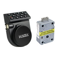
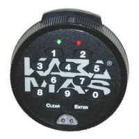
Figure 1 - Slide Bolt Lock Parts
Front Cover &
Keypad Assembly
Cable
Lock Case
Assembly
Lock Case
Mounting
Screws (3)
Front Cvr
Mounting
Screws (3)
Spindle
Dial
Mounting
Screw
Dial
Dial Label
Figure 4
Keypad/
Base Mtg
Screws (2)
.136 in. MIN. CLEARANCE
.062 in. MIN. CLEARANCE
RADIUS
STRIKE
REVERSE
ANGLE
STRIKE
CONTACT POINT
IS NOT ALLOWED
TO BE BEHIND
ROLLER CENTER LINE
FORWARD
ANGLE
STRIKE
STRAIGHT
STRIKE
.300 in. REFERENCE
CASE TO CENTER LINE
0.000 TO .080 in. MAX
RECOMMENDED
STRIKE
CONTACT POINT
STRIKE
CONTACT POINT
BEHIND ROLLER
CENTER LINE
ALLOWED
ROLLER CENTER LINE
NOT ALLOWED
ROLLER CENTER LINE
STRIKE
CONTACT
POINT
STRIKE
CONTACT
POINT
15° MAX
.495
STRIKE
Figure 3 - Roller Slide Bolt Clearances, Strike Types & Contact Points
Basic Tools and Materials Needed
• Medium Phillips head screwdriver
(#2) (recommend magnetized tip)
• ESD wrist band
Recommended, but not required:
• Torque screwdriver (30 inch-
pounds/3.4 newton-meters
capacity)
• Loctite
®
262 (Red) for use on lock
case mounting screws
WARNING: Kaba Mas locks are
protected from 25,000 V Electro-
static Discharge (ESD) damage
when correctly installed. Follow
these precautions to avoid ESD
damage when installing the lock:
• Handle the keypad assembly by
the outer edge only.
• Use an ESD wrist band grounded
to the lock or container during
installation.
Figure 2 - Square Nose Slide Bolt Clearances and Positioning
Not Shown in Photo: Nylon Dial Spacer, Metal Dial Mounting Washer, Lubricant
Document # 3046.025 Rev. B - 12/06
Prepare for New Installation of the Lock
(If Required)
1. Using the lock parts along with the template
provided, establish the exact location for the drilled
and tapped holes.
Caution:
The lock case must be mounted exactly
according to the template if mounted over the cable
routing hole. Otherwise, the lock case must be mounted
so that no part of the case covers the cable routing
hole.
2. The spindle hole diameter can be a minimum of
.406” (10.3mm) to a maximum of .438” (11.1mm).
The .406” (10.3mm) diameter is recommended.
Spindle hole must be deburred.
3. The keypad/base assembly mounting screws
require drilled and tapped holes to 3/8” (9.5mm)
depth if possible (minimum 1/4” or 6.4mm depth
required.) Drill either the two horizontal mounting
holes or the two vertical holes.
4. When mounting the lock unit (i.e., integrating it
in a boltwork), make sure that the lock bolt has
clearance to freely move to its end positions and
that the shifting force works only in the axial
direction (direction of movement). Lateral forces
should not be exerted on the lock. A minimum
clearance of 1/16” (1.6mm) is required between the
bolt roller/nose and the inside edge of the strike.
Refer to Figures 2 and 3.