Do you have a question about the Kaco Powador 2500xi and is the answer not in the manual?
Instructions for passing on and storing operating and installation documents.
Explanation of safety symbols like DANGER, WARNING, CAUTION, NOTE, ACTION, IMPORTANT.
Documentation of compliance with EU directives for EMC and Low Voltage.
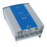
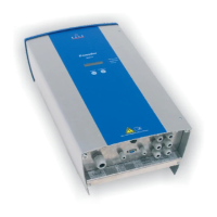
Location of the unit's designation on the support plate.
Requirements for installation by authorized electricians and safe operation.
Prohibition of modifications and consulting electricians for changes.
Procedures for inspecting and handling the inverter during transport.
Description of the unit's purpose and limitations for safe operation.
Details on the warranty period, claims, and exclusions.
Contact information and approach for service and fault remedy.
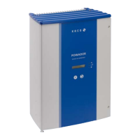
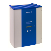
Identification of controls, displays, and their functions.
Explanation of the meaning of the three status LEDs.
Functionality of keys for display navigation and parameter configuration.
Details on navigating and viewing measured values in display mode.
How to switch to and use the configuration mode for settings.
Function and operation of the internal DC disconnector.
How to activate the display to retrieve values after dark.
Transmitting operating data to a computer via a serial interface.
Enabling remote monitoring of installations via the RS485 interface.
Features of the backlit LCD display for measured values.
Instructions for passing on and storing operating and installation documents.
Explanation of safety symbols like DANGER, WARNING, CAUTION, NOTE, ACTION, IMPORTANT.
Relevant standards like IEC 60364-7-712:2002.
Requirements for installation to comply with local rules.
Requirements for installation by authorized electricians and safe operation.
Prohibition of modifications and consulting electricians for changes.
Procedures for inspecting and handling the inverter during transport.
Description of the unit's purpose and limitations for safe operation.
Details on the warranty period, claims, and exclusions.
Contact information and approach for service and fault remedy.
Technical specifications for the inverter's electrical input.
Technical specifications for the inverter's electrical output.
Electrical performance characteristics of the inverter.
Mechanical and environmental specifications of the inverter.
Parameters and settings that vary by country.
Table detailing grid connection parameters by country.
Menu structure for country-specific parameter configuration.
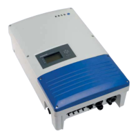
List of items included in the inverter package.
Guidelines for selecting PV modules and calculating voltage.
Integrated monitoring and protective functions of the inverter.
Criteria for choosing a suitable installation location for the inverter.
Step-by-step instructions for mounting the inverter.
General information and safety precautions for electrical hookup.
Details on single-phase grid connection and recommended cable cross-sections.
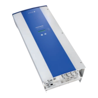
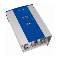
Connecting the PV generator using various connector types.
How to connect the potential-free relay contact for fault signaling.
Connecting external displays or devices to the SO pulse output.
Wiring instructions for connecting multiple inverters via RS485.
Procedures for putting the inverter into operation after installation.
How to set operating parameters via the configuration menu.
Overview circuit diagrams for grid-connected PV installations.
Guidelines for connecting multiple inverters to the grid.
Special considerations for the 5000xi model in multi-inverter setups.
Statement of compliance with EU directives and standards.
Certificate of compliance from Bureau Veritas.
| Rated Output Power | 2500 W |
|---|---|
| Maximum DC Power | 3000 W |
| Number of MPP Trackers | 1 |
| Maximum AC Output Power | 2500 W |
| Maximum AC Power | 2500 W |
| Cooling | Convection |
| Protection Degree | IP54 |
| Model | Kaco Powador 2500xi |
| Type | Transformerless string inverter |
| Maximum DC Input Power | 3000 W |
| Nominal AC Output Voltage | 230 V |
| AC Voltage | 230 V |
| AC Output Frequency | 50 Hz |
| Operating Temperature Range | -20°C to +60°C |