S
Stephen MillerAug 16, 2025
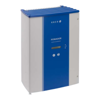
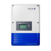
What to do if my Kaco Powador 3200 is active but does not feed into the grid even when the insolation is sufficient?
- RreyesmaryAug 16, 2025
If a fault such as line failure, overtemperature, or overload causes a feed-in interruption, the Kaco Inverter will check the line parameters for a period. The time it takes to switch back on may vary by country according to standards and regulations and can take several minutes. If the inverter shuts down regularly over several weeks (more than 10 times per day), contact your solar installer. Consult the fault signals for an explanation of the display error texts.