7
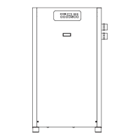
3. Check interface panel.
NOTE: Interface panel will scroll through three screens
(Current Time/Operating Status, Hours to Service and Total
Operating Hours).
a. Verify that current time is correct.
b. Check HRS TO SERVICE: this indicates time remaining
until service is required; allow time for required
maintenance items to be ordered.
c. Check operating status:
MANUAL OVERRIDE - Dryer is either running
continuously (not being controlled by the scheduled
on/off times) or the refrigeration compressor has
been shut off using the ‘On/Off’ button.
SCHEDULE RUNNING - Refrigeration compressor
is being turned on and off by the monitor per-
programmed schedule (see B.3. to set schedule).
d. Check Temperature indicator - indicator should read
in the green area.
e. Check Alarm/Service light If illuminated, check
Interface panel.
1) If SERVICE DRYER appears, scheduled maintenance
time has elapsed (HRS TO SERVICE is 0). Perform
needed service and reset service interval (see B.3.).
2) If ALARM appears, a dryer fault is indicated; see
Troubleshooting Guide for possible remedies.
After fault correction push Reset button to turn
Fault alarm off.
Type of FAULTS:
LOW PRESSURE - the refrigeration compressor
control circuit has opened because of low suction
pressure.
HIGH PRESSURE - the refrigeration compressor
control circuit has opened because of high head
pressure. The high pressure switch must be reset
manually once the fault is corrected. Red reset
button is located on pressure switch inside unit.
HIGH TEMPERATURE - compressed air temperature
is above the set point.
COMPRESSOR-Normallyopen(NO)auxiliary
contact on the compressor contactor is open
when the dryer is on.
HEATER-Normallyclosed(NC)auxiliarycontacton
the compressor contactor is open when the dryer
is off.
TEMP SENSOR - Occurs if the temperature sensor
circuit is open or shorted. If open, the left-most
LED in the temperature display will be illuminated.
If shorted, all the LEDs in the temperature display
will be illuminated.
DRAIN - electric drain contains a high water level
alarm that activates if drain fails to discharge.
f. Check drain operation - push Drain (push-to-
test)buttontoenergizeelectricdrain.Aowof
condensate and/or air should be present at the drain
outlet.
E. Using the RS-232 port
The RS-232 port is used to monitor dryer operation from
a host computer. A (1 to 1) DB-9 cable is required to
connect dryer and computer. For PC connections, data
is transmitted on pin 2, received on pin 3, ground is pin
5, pins 7 and 8 are jumpered at dryer.
Operationisatxedbaudrateof9,600;asynchronous
format is 8 bit, no parity, 1 stop bit (“8,N,1”). No check
sum or error correction values are provided. If required,
request status string two (or more) times and compare
for agreement.
Request data by sending ASCII ? character (3FH).
Response may take up to two seconds as certain
processing functions may require completion before
serial port is acknowledged.
Dryer responds with line feed (0AH), carriage return
(0DH), and character string: (1), (2), (3), (4), (5), (6), (7), (8), (9)
(1)=STX(start-of-textcharacter,mayappearasasmiley
face or some other character
(2) = 108, Control board ID
(3) = 0 or 1, Compressor running status (0=off, 1=on)
(4) = M or S, Operating Mode (M= MANUAL OVERRIDE, S =
SCHEDULE RUNNING)
(5)=xxxx,HOURSTOSERVICE
(6)=xxxxxx,TOTALHOURS
(7)=xx,AlarmorServiceCode(0=noalarm,30=LOW
PRESSURE ALARM, 31=HIGH PRESSURE ALARM,
32=COMPRESSOR ALARM, 36=HIGH EVAP TEMP ALARM,
37=HEATER ALARM, 38=DRAIN ALARM, 39=SERVICE
DRYER, 41=TEMP SENSOR ALARM)
(8) =xx.x,Evaporatortemperature(°F)
(9) =ETX,(end-of-textcharacter,mayappearasaheart
or some other character)
 Loading...