Do you have a question about the Kaisai KMK-60RY1 and is the answer not in the manual?
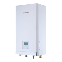
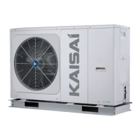
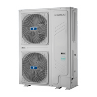
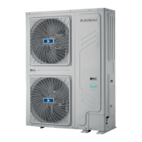
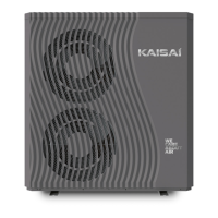
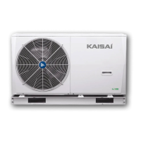
Details the capacity ranges for outdoor units and their compatible hydronic box models, including specific model names and ratings.
Provides visual representations of the outdoor units and hydronic box models to identify their design and physical characteristics.
Illustrates the internal arrangement of key components within both outdoor and hydronic units, with detailed labeling.
Presents schematic diagrams of refrigerant and water piping, detailing connections, valves, and components for system understanding.
Visually depicts the refrigerant flow paths during different operational modes such as heating, cooling, and defrosting.
Describes the reasons and conditions that cause the system to cease operation, including abnormal shutdowns and setpoint achievement.
Explains the control strategies for the system when idle, focusing on components like the crankcase heater and water pumps.
Details the controlled startup sequences for the compressor, including delays and temperature-dependent programs.
Outlines component control logic during standard heating and cooling cycles, specifying parameters for compressor, fan, and EXV.
Covers various safety protections like high/low pressure, voltage, and temperature limits that prevent system damage.
Explains unique operational modes such as oil return, defrosting, fast DHW, and multi-zone control for specific applications.
Identifies temperature sensor locations and describes their critical role in regulating system performance and safety.
Visually guides users through the internal layout of electric control boxes in outdoor and hydronic units, highlighting PCBs and modules.
Details the main printed circuit boards (PCBs) for both outdoor and hydronic systems, listing connector functions and layouts.
Provides a comprehensive list of error codes, their meanings, and associated causes for effective troubleshooting.
Offers step-by-step procedures and solutions for diagnosing and resolving common system errors and malfunctions.