© 2003 D 360e - 06/03 14 of 20
BOILER SENSOR (RETURN / SUPPLY)
The Boiler Sensor DIP switch selects the installation location for the boiler sensor. When the boiler sensor is installed on the
supply side of the boiler loop, the DIP switch must be set to Supply. The boiler aquastat should be set at least 20 °F (11 °C)
higher than the required design boiler water temperature. The boiler is controlled as described in section C.
For systems where the 360e provides a heat demand to an external boiler control, the boiler sensor should be installed on the
return side of the boiler loop. When the boiler sensor is installed on the return side of the boiler loop, the DIP switch must be
set to Return. The 360e enables the boiler when the position of the mixing valve exceeds the boiler enable DIP switch setting.
The Boiler contact is controlled as described in section C. The boiler’s operating temperature is controlled by its aquastat, or
an external boiler reset control.
The quick setup can be used for both outdoor reset and setpoint operation. To enter the installer programming mode, set the
Advanced / Installer DIP switch to Installer.
OUTDOOR RESET
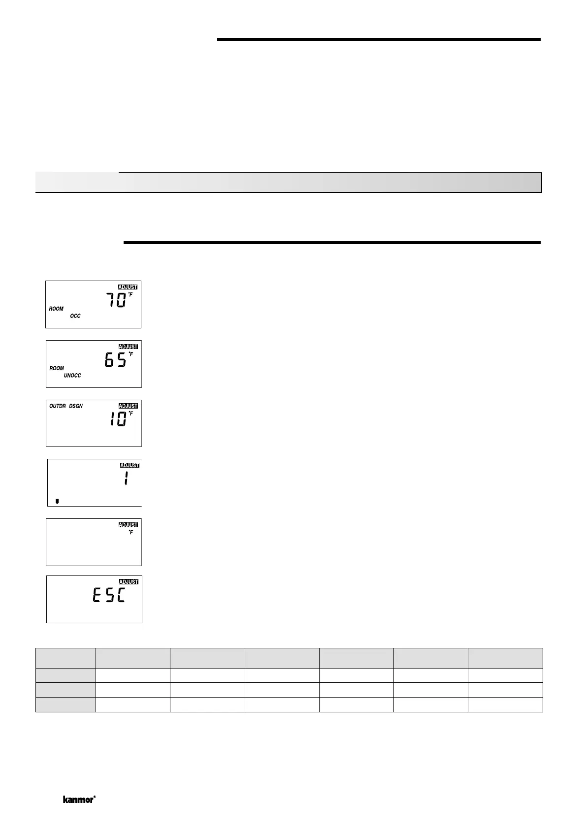
Access the ADJUST menu by pressing and holding simultaneously for 1 second, the Item, ▲ and ▼ buttons. The display will
now show the word ADJUST in the top right corner.
The ROOM OCC adj ustmen t is the fir st item di splayed. Us e the ▲ or ▼ button to set the ROOM temp erature.
The ROOM OCC setting is set to the desired room air temperature during the occupied (Day) mode.
Note: To increase or decrease space temperature during the occupied (Day) mode, only adjust the
ROOM OCC setting.
Press and release the Item button to advance to the ROOM UNOCC adjustment. Use the ▲ or ▼
button to set the desired temperature. The ROOM UNOCC setting is set to the desired room air
temperature during the unoccupied (Night) mode.
Note: To increase or decrease space temperature during the unoccupied (Night) mode, only adjust
the ROOM UNOCC setting.
Press and release the Item button to advance to the OUTDR DSGN adjustment. Use the ▲ or ▼
button to set the outdoor design temperature. The OUTDR DSGN setting is set to the typical coldest
temperature of the year.
Press and release the Item button to advance to the Terminal Unit adjustment. Use the ▲ or ▼
button to select the desired terminal unit. The terminal unit number corresponds to the type of termi-
nal that is being used. The table below lists the terminal units and their default values.
Press and release the Item button to advance to the units adjustment. Use the ▲ or ▼ button to set
the scale to °F or °C.
To exit the ADJUST menu, press and release the Item button to advance to the ESC item. Then
either press the ▲ or ▼ button, or leave the buttons alone for 20 seconds.
Quick Setup
Terminal
TERMINAL
UNIT
HIGH MASS RADIANT
(1)
LOW MASS RADIANT
(2)
FANCOIL
(3)
FIN-TUBE CONVECTOR
(4)
RADIATOR
(5)
BASEBOARD
(6)
MIX DSGN
MIX MAX
MIX MIN
120°F (49°C)
140°F (60°C)
OFF
140°F (60°C)
160°F (71°C)
OFF
190°F (88°C)
210°F (99°C)
100°F (38°C)
180°F (82°C)
200°F (93°C)
OFF
160°F (71°C)
180°F (82°C)
OFF
150°F (66°C)
170°F (77°C)
OFF
 Loading...