KT-100 Installation Manual
7
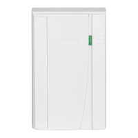
To connect inputs:
1.
Connect devices between inputs Z1 to Z4 and COM.
2.
Connect resistors (included with KT-100) for all inputs
5.6K ohm (if selected).
NOTE: Inputs can be defined with none or one end-of-line resis-
tor according to parameters defined in your EntraPass Special
Edition software.
Step 7•
Connecting Readers and Keypads
The maximum allowable distance between the readers and the
KT-100 controller varies by reader type. Please consult the
reader manual for details.
WARNING! Connecting the red wire lead (or power
lead) of a 5VDC reader to the 12VDC terminal may
damage the reader. Refer to the reader installation
procedure for proper power connection. Up to 2
readers can be connected to a KT-100. They can be
installed on one door to control both entry and exit.
To connect the reader (entry and exit) refer to
the diagram below:
NOTE:
◗ The 12 VDC auxiliary power can also be used to power
low current audible devices usually located at the
controlled door. Auxiliary outputs can be connected to
readers & local warning devices to be used for visual and
audible signals.
◗ Auxiliary output “LED” provides visual feedback of
access operation; auxiliary output “BUZ” can activate
audible warning devices, such as T.REX, to signal door
alarms.
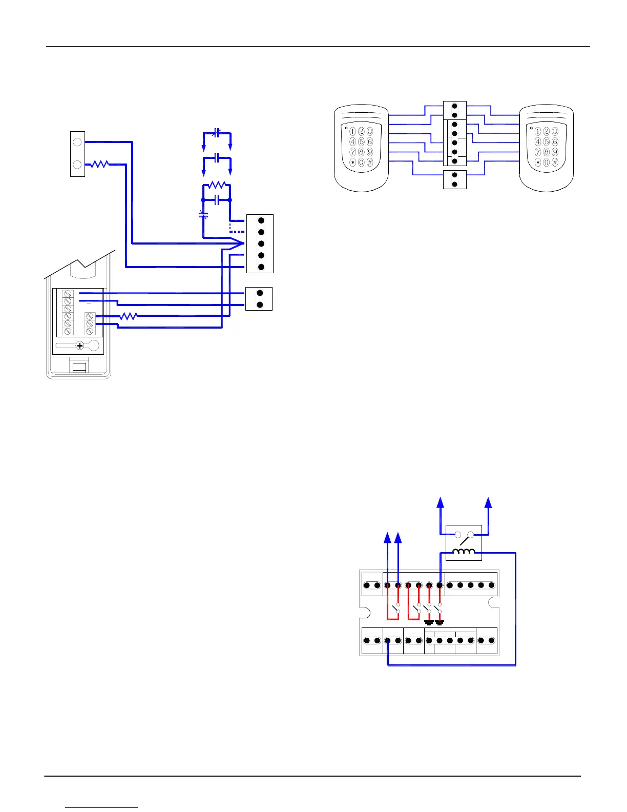
Step 8•
Connecting Control Relay Outputs
The KT-100 provides two opto-isolated contacts (R1 & 2) and
two control outputs (R3 & 4). R1 & 2 can be used as either as
dry contacts.
◗
R1 & R2: maximum voltage = 30 volts AC/DC;
maximum current = 100 mA total; (R1 & R2).
◗
R3 & R4: maximum voltage = 12 volts DC;
maximum current (each relay) 25 mA
NOTE: Use a KT-RM1 (optional) to switch larger currents or
voltages or to supply a dry contact.
Step 9•
Connecting the Tamper Switch
Optionally, a tamper switch may be installed on the unit to
detect unauthorized opening of the cabinet. For this purpose,
you may use the MUSB1 box for surface mount (Optional -
Kantech part # KT-100TAMP).
DOOR REX COM AUX AUX
INPUTS
Z1 Z2
Z3 Z4
Door Contact
T.REX
C1 NC1 NO1
-++ - TAMPER
POWER BUZZER
NC or NO Dry contact
Controller defined witho
End of Line Resistor
NC
or
NO
Dry contact
Controller defined with
End of Line Resistor
Optional
5,6K End of Line Resistor
Additional Zone Inputs
(Z3 & Z4)
PWR OUT
12VDC
+-
Optional
5,6K End of Line Resistor
PWR OUT
12VDC
PWR
ENTRY EXIT
LED BUZ+5V WHT GRN WHT GRN
OUTPUTS
CARD READERS
+-
500mA Max
IOProx
Card Reader
IOProx
Card Reader
KT-100
EXIT READERENTRY READER
BLUE
BROWN
GREEN
WHITE
RED
BLACK
BLUE
BROWN
GREEN
WHITE
RED
BLACK
Relays Outputs
Internal
Equivalent
Circuits
R1 R2 R4R3
RELAYS
PWR IN
12VDC
PWR OUT
12VDC
LOCK
PWR
ENTRY EXIT
LED BUZ
+-
+5V WHT GRN WHT GRN
OUTPUTS
CARD READERS
750mA Max
+-
500mA Max
--
NO NC
RS-485
R1 R2 R3 R4
DOOR REX COM
AUX
AUX
INPUTSRELAYS
X+ X-
Z1
Z2
Z3 Z4
12 volts DC
Relay
30 volts
AC/DC
Contact