KT-100 Installation Manual
9
Section 3: Appendix
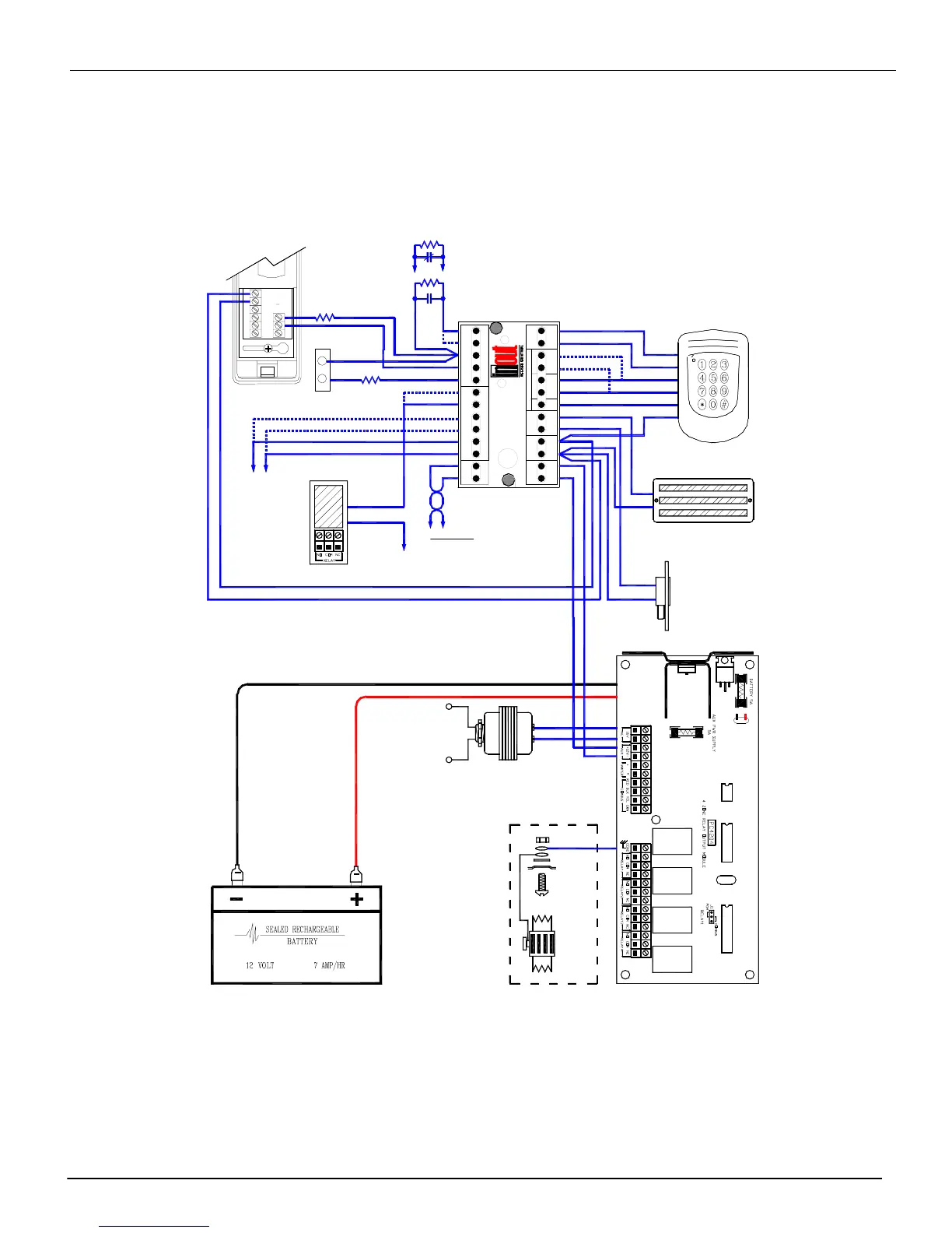
Typical KT-100 Wiring Diagram
PWR IN
12VDC
PWR OUT
12VDC
LOCK
PWR
ENTRY EXIT
LED BUZ
+-
+5V WHT GR N WHT GRN
OUTPUTS
KT-100
CARD READERS
750mA M ax
+-
500mA M ax
--
MADE IN CANADA
NO NC
RS-485
R1 R2 R3 R4
DOOR REX
COM
AUX AUX
INPUTSRELAYS
X+ X-
Z1
Z2
Z3 Z4
ACCESS CONTROLLER
This device complies with Part 15 of the FCC rules.
Operation is subject to the following two conditions:
(1) This device may not cause harmful interference,
and (2) This device must accept any interference
received, including interference that may cause
undesired operation.
BLUE
BROWN
GREEN
WHITE
RED
BLACK
Optional Exit Reader
Door Locking Device
12 Volts DC 250 mA MAX.
Electrical Mag-Lock
12 Volts DC 250 mA MAX.
(IF NOT USED, CONNECT A 1000 OHMS
RESISTOR BETWEEN NC AND +12V)
IOProx Card
Reader
Entry Reader
Door Contact
WASHER
Sealed Acid-Lead
12 Volts Battery
7 A/h Maximum
KANTECH # KT-BD7-12
120/220 VOLTS 40VA
CLASS 2
(WIRE-IN)
Plug-in also available
Do not connect to receptacle
controlled by a switch
EARTH
GROUND
SCREW
CASE
4 Relays Module PC4204
NUT
RS485 Network
to others KT-100s
or
to PC Workstation
via USB/485 interface
T.REX
C1 NC 1 NO1
-++-TAMPER
POWER BUZZER
NC Dry contact
Controller defined without
End of Line resistor
NO Dry contact
Controller defined with
End of Line resistor
Opto-Isolated Contact
120 Volts AC/DC
100 mA Max. Load
Optional
End of Line resistor
Positive
Negative
12 Volts DC
Open-Collector
25 mA Max.
+12VDC
 Loading...