15
KT-PC4204 - 4-Relay and Additional Power Supply Module
KT-PC4204 Introduction
The KT-PC4204 module is an output module with four
programmable relays. This module can be used to
“repower” the Combus. The KT-PC4204 can also be used
for elevator control.
NOTE: Do not use any power supply other than the KT-
PC4204 module to repower the Combus. If a power
supply other than the KT-PC4204 is used, the
Combus repower function will not operate as
intended.
KT-PC4204 Specifications
• Current draw: 30 mA (from Combus)
• 40 VA 16 VAC transformer required
• Maximum 7 A/h battery required
• Connects to the controller via 4-wire Combus
• Four programmable relay contacts rated 2 A, 30 VDC
• AUX current: 1.0 A max.
• Tamper contact input
• Can be used to repower the Combus
Unpacking the KT-PC4204
The KT-PC4204 package should include the following
parts/items:
• One KT-PC4204 circuit board
• One ground wire assembly
• Five plastic standoffs
• One 5 A replacement fuse
Mounting the KT-PC4204
The KT-PC4204 should be located inside a compatible
cabinet (Kantech part no. KT-4051CAB), mounted in a dry,
secure location. Preferably, it should be placed at a
convenient distance from the connected devices. Perform the following steps to mount the unit:
1. Push the five plastic standoffs through the mounting holes on the back of the cabinet.
2. Secure the cabinet to the wall in the desired location. Use appropriate wall anchors when securing the cabinet to dry wall,
plaster, concrete, brick or other surfaces.
3. Press the circuit board into the plastic standoffs to secure the module to the cabinet.
NOTE: Wiring may take place once the unit is mounted.
Installation and Wiring
Before wiring the unit, ensure that all power (AC transformer and battery) is disconnected from the KT-315 controller. Perform
the following steps to complete wiring:
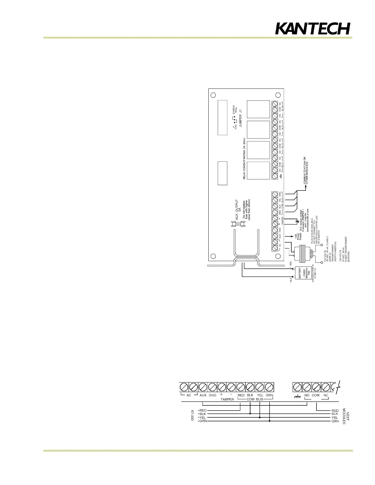
1. Connect the four Combus wires to the KT-PC4204. Connect the red, black, yellow and green Combus wires to the RED,
BLK, YEL and GRN terminal respectively.
2. If the module is used for Combus Repower,
connect the Combus wires according to the
diagram on the right. Note that for this option,
Jumper J1 must also be set to “Combus Relay”.
3. Complete all output wiring.
4. Connect the external tamper switch, if used.