EasyManua.ls Logo

Kärcher BR 250 R - User Manual

Kärcher BR 250 R
171 pages
Print Icon
To Next Page IconTo Next Page
Loading...
Service Manual 08.2007
5.906-252.0
BR/BD 100/250 R / RI
BR/BD 120/250 R / RI
1.480- . . .
Service Manual

Table of Contents

Questions and Answers

  • J
    Jessica MathisSep 7, 2025
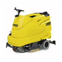
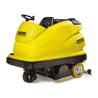
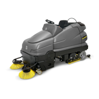
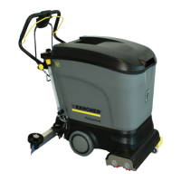
    What to do if the brush head cannot be raised or lowered on a Kärcher Floor Machine?
    • S
      spayneSep 7, 2025
      If the brush head on your Kärcher Floor Machine cannot be raised or lowered: – Check and replace fuse (F4) if necessary. – Ensure the lifting mechanism is not blocked. – Test the program selector switch (S9) and replace if necessary, using test mode. – Test the lifting motor (M20) and replace if necessary, using test mode. – Test the lifting module printed circuit board (A4) and replace if necessary, using test mode.
  • S
    Susan DaltonNov 25, 2025
    What to do if there is no or too little water supply in Kärcher Floor Machine?
    • D
      danielmaynardNov 25, 2025
      If your Kärcher Floor Machine has no or too little water supply, try the following: – Top up the fresh water tank. – Check and clean the water filter. – Check the water hose to the brush head, removing any blockages or kinks. – Test and replace the program switch (S9) if necessary, using test mode. – Test and replace the float switch of the dirty water tank (S11) if necessary, using test mode. – Test and replace the level sensor of the fresh water tank (B2) if necessary, using test mode. – Test the function of the metering valve (Y2) and replace if necessary, using test mode. – Test the water pump (M5) and replace if necessary, using test mode. – Check cable connections and replace defective cables. – Test the cleaning module printed circuit board (A3) and replace if necessary, using test...
  • C
    Carl VasquezNov 19, 2025
    Why won't my Kärcher Floor Machine unit start?
    • C
      christinajonesNov 19, 2025
      If your Kärcher Floor Machine unit won't start, here are some things you can check: – Ensure the central battery plug (X1) is correctly inserted, check it, and replace it if necessary. – Check, charge, or replace the battery (G1). – Inspect fuses F1 and F1, replacing any that are defective. – Check or replace the key switch (S0). – Check, unlock, or replace the EMERGENCY STOP switch (S1). – Test and potentially replace the seat sensor (S10) using the tester mode. – Test and potentially replace the program switch (S9) using the test mode. – Test and potentially replace the direction of travel switch (S2) using the test mode. – Check or replace the main relay (K1). – Test and potentially replace the magnetic sensor of the drive pedal (B1) using the test mode. – Test the connection cable mod...
  • P
    Paul CookSep 18, 2025
    Why main and side brushes do not turn on Kärcher BR 250 R Floor Machine (RI version)?
    • K
      Kelly AlvarezSep 18, 2025
      If the main and side brushes on your Kärcher Floor Machine (RI version with pre-sweeping unit or side brush option) do not turn: – Check for any mechanical blockage and repair it. – Check and replace the program switch (S9) if needed. – Check and replace the pre-sweeping system (S6) switch if needed. – Check and replace the clean module pre-sweeping system (F6) if needed. – Check and replace the side brush motor (M10, M11, M41, M42) if needed. – Check and replace the clean module (F3) safety lock if needed. – Check and replace the brush motors (M2, M3, M5) if needed. – Check and replace the clean module (A3/1) if needed.
  • S
    Samantha LaraSep 16, 2025
    What to do if main brush cannot be lifted or lowered on Kärcher BR 250 R Floor Machine (RI version)?
    • L
      Lisa LeeSep 16, 2025
      If the main brush on your Kärcher Floor Machine (RI version with pre-sweeping unit) cannot be lifted or lowered: – Check for any mechanical blockage and repair it. Check the function of the side brush suspension (spring, Bowden cable, deflection pulley). – Check and replace the lift module of the pre-sweeping system (F6) if needed. – Check and replace the pre-sweeping system (S6) switch if needed. – Check and replace the program switch (S9) if needed. – Check and replace the micro-switch of the lower pre-sweeping system (S50) if needed. – Check and replace the micro-switch of the upper pre-sweeping system (S51) if needed. – Check and replace the lifting motor of the pre-sweeping system (M50) if needed. – Check and replace the lift module of the pre-sweeping system (A4/2) if needed.
  • E
    Emily BradfordSep 14, 2025
    What to do if side brushes cannot be lifted or lowered on Kärcher BR 250 R Floor Machine (RI version)?
    • M
      Megan RobertsonSep 14, 2025
      If the side brushes on your Kärcher Floor Machine (RI version with pre-sweeping unit or side brush option) cannot be lifted or lowered: – Check for any mechanical blockage and repair it. Check the function of the side brush suspension (spring, Bowden cable, deflection pulley). – Check and replace the side brush lift module (F8) safety lock if needed. – Check and replace the pre-sweeping system (S6) switch if needed. – Check and replace the program switch (S9) if needed. – Check and replace the micro-switch of the lower side brush (S40) if needed. – Check and replace the micro-switch of the upper side brush (S41) if needed. – Check and replace the lifting motor of the side brush (M40) if needed. – Check and replace the lift module of the side brush (A4/1) if needed.
  • J
    Jennifer BrooksSep 12, 2025
    What to do if Kärcher Floor Machine raises dust or does not vacuum (RI version)?
    • K
      Kevin RiveraSep 12, 2025
      If your Kärcher Floor Machine (RI version with pre-sweeping unit) raises dust or doesn't vacuum: – Check and replace the side brush and main brush if needed. – Verify the direction of rotation of the main brush and properly connect the electrical connecting cables (plus/minus). – Check and replace the seal of the filter case of the debris container if needed. – Check and replace the round filter if needed. – Check, adjust, or replace sealing lips/strips. – Check and replace the fan drive belt if needed. – Check and adjust the pre-sweeping unit for parallelism. – Check and replace the clean module pre-sweeping system (F6) safety lock if needed. – Check and replace the fan motor (M13) if needed. – Check and replace the clean module pre-sweeping system (A3/1) if needed.
  • L
    Lawrence PerrySep 12, 2025
    How to improve poor braking effect on Kärcher BR 250 R Floor Machine?
    • V
      Vincent BallardSep 12, 2025
      To improve a poor braking effect on your Kärcher Floor Machine: – Test the electromagnetic brake (Y1) and adjust or replace if necessary, using test mode. – Test the driving module printed circuit board (A2) and replace if necessary, using test mode.
  • D
    David RivasSep 9, 2025
    Why won't the brush motor start on my Kärcher Floor Machine?
    • J
      Jasmine JuarezSep 9, 2025
      If the brush motor on your Kärcher Floor Machine isn't starting: – Check and replace fuse (F3) if necessary. – Test the brush motor (M2, M3) and replace if necessary, using test mode. – Check cable connections and remove defective cables. – Test the cleaning module printed circuit board (A3) and replace if necessary, using test mode.
  • D
    dowensAug 22, 2025
    What to do if the suction motor won't run on my Kärcher BR 250 R?
    • K
      Kimberly MendezAug 22, 2025
      If the suction motor on your Kärcher Floor Machine isn't running, consider these possible solutions: – Ensure the suction beam is not raised. – Check if the dirty water tank is full. – Check and replace fuse (F3) if necessary. – Test and replace the float switch (S12) if necessary, using test mode. – Test and replace the program selector switch (S9) if necessary. – Test and replace the suction motor (M4) if necessary, using test mode. – Check cable connections, removing any defective cables. – Test the cleaning module printed circuit board (A3) and replace if necessary, using test mode.

Summary

Foreword

Equipment Features

Technical Features (BR;BD 100;250 R)

Details the technical specifications for the BR/BD 100/250 R model, covering drive system, sweeping system, and electrical system.

Technical Features (BR;BD 100;250 RI)

Details the technical specifications for the BR/BD 100/250 RI model, highlighting its pre-sweeping unit and differences from the R version.

Technical Features (BR;BD 120;250 R, BR;BD 120;250 RI)

Details technical specifications for BR/BD 120/250 R and RI models, including Bp and BP Pack versions and working width.

View from the Left-Hand Side

Illustrates and labels key components of the machine visible from the left-hand side.

View from the Right-Hand Side

Illustrates and labels key components of the machine visible from the right-hand side.

Rear View

Illustrates and labels key components of the machine visible from the rear.

Technical Features

Wheel Hub Motor (M1)

Describes the wheel hub motor, including its components, freewheeling lever, and notes on transport.

Brush Head

Details the brush head components for BR and BD versions, including mounting parts and lifting motor.

Suction Beam

Describes the suction beam, its components, rubber strips, and lifting mechanism.

Suction Motor (M4)

Explains the function and location of the suction motor, including removal steps.

Water System

Details the water filter, water pump, cleaning agent metering pump, and optional cleaning agent canister.

Dirty Water Tank with Recycling Function (Optional)

Describes the dirty water tank, float switch, and the optional recycling mode lever.

Control Panel

Illustrates and lists the functions of various buttons, switches, and indicators on the control panel.

Program Switch (S9)

Explains the 8 switching positions of the program switch and their corresponding functions.

Seat Sensor (S10) and Distribution Box (EXT.X1)

Describes the integrated seat sensor safety function and the distribution box connections.

Battery (Low-Maintenance) with Filling System

Details the battery configuration, filling system, and central plug connections.

Battery Charger

Provides operating instructions and indicator light explanations for the battery charger.

Side Brush (Optional)

Illustrates the side brush suspension, motors, and optional features.

Pre-sweeper Unit (BR;BD 100;250 RI only)

Details the pre-sweeper unit, its components, and its integration with the machine.

Unit Functions

Functional Diagram

Provides a schematic overview of the machine's functional components and their interconnections.

Brush Head Mounting Parts

Details the mounting components for the brush head, distinguishing between BR and BD versions.

Brush System - Contact Pressure Adjustment

Explains how brush contact pressure is adjusted via the lifting motor and current consumption.

Pre-sweeper Unit Functional Diagram (BR;BD 100;250 RI only)

Illustrates the functional diagram of the pre-sweeper unit for RI models.

Operator and Service Program Overview

Outlines operator functions, service program availability, and the function of info buttons.

Operator Functions

Details operator functions, test modes for service technicians, and display modes.

Modular Electronic Control Circuits

Modular Electronic Control Circuits

Provides an overview of the modular system and its network configuration.

Modular System BR;BD 100;250 R

Illustrates the modular system architecture for the BR/BD 100/250 R basic unit.

Modular System BR;BD 100;250 R with Side Brush (Optional)

Illustrates the modular system for BR/BD 100/250 R with an optional side brush.

Modular System BR;BD 100;250 RI

Illustrates the modular system architecture for the BR/BD 100/250 RI model.

Emergency Operation (Driving)

Explains emergency driving procedures by connecting the drive module directly to the head CPU.

Control Panel Components

Shows the view from below of the control panel, highlighting the warning/information and head CPU modules.

Lifting Module (A4) and Accessories Module (A5)

Details the lifting module (A4) and accessories module (A5), including their terminal strips and PCBs.

Driving Module (A2) and Cleaning Module (A3)

Details the driving module (A2) and cleaning module (A3), including their printed circuit boards and connections.

Lifting Module (A4;1) and Cleaning Module (A3;1) (Optional)

Details optional lifting module (A4/1) and cleaning module (A3/1), including PCBs and connections.

Service Module (A9)

Describes the service module for diagnostics, parameterization, and firmware updates.

Basic Settings and Service Procedures

Test Mode (Head CPU from Version 1.2)

Details accessing the test mode for machines with head CPU version 1.2.

Access to the Test Mode (with Program Switch S9, Position 1)

Procedure for accessing test mode using program switch S9 position 1 (Drive).

Access to the Test Mode (with Program Switch S9, Position 2)

Procedure for accessing test mode using program switch S9 position 2 (Scrub-Vacuum).

Current Measurement with Switching On;Off Function

Describes how to measure current and perform on/off functions for components in test mode.

Access to the Test Mode (with Program Switch S9, Position 3)

Procedure for accessing test mode using program switch S9 position 3 (Wet Scrub).

Access to the Test Mode (with Program Switch S9, Position 4)

Procedure for accessing test mode using program switch S9 position 4 (Vacuum).

Access to the Test Mode (with Program Switch S9, Position 5)

Procedure for accessing test mode using program switch S9 position 5 (Polish).

Accelerator Pedal Calibration

Step-by-step guide for calibrating the accelerator pedal in test mode.

Illuminated Symbol Test

Procedure for testing all illuminated symbols and LEDs on the machine.

Service-Operator Menu

Details how to access and navigate the service-operator menu for diagnostics and parameter setup.

Test Mode (Head CPU up to Version 1.1)

Details accessing the test mode for machines with head CPU version up to 1.1.

Access to the Test Mode ORIGINAL

Procedure for accessing the test mode with the original settings.

Test Mode - Drive Units

Details testing individual drive units (motors, pumps, valves) via the program switch.

Test Mode - Lifting Motors

Details testing lifting motors for brush head and suction beam via the program switch.

Test Mode - Calibration

Details performing calibration tests for various machine functions.

Setup Menu

Provides access to machine setup menus for parameter configuration.

Setup Menu (Head CPU from Version 1.2)

Details accessing the setup menu for machines with head CPU version 1.2.

Access to the Setup Menu

Procedure for accessing the main setup menu via the info button.

System Menu and Driving Module Parameters

Details system and driving module parameters accessible through the setup menu.

Cleaning Module and Lifting Module Parameters

Details cleaning and lifting module parameters accessible through the setup menu.

Setup Menu (Head CPU up to Version 1.1)

Details accessing the setup menu for machines with head CPU version up to 1.1.

Access to the Setup Menu ORIGINAL

Procedure for accessing the setup menu with original settings.

System Menu and Driving Module Parameters ORIGINAL

Details system and driving module parameters with original settings.

Cleaning Module and Lifting Module Parameters ORIGINAL

Details cleaning and lifting module parameters with original settings.

Save Changed Adjustable Parameters

Procedure for saving adjusted parameters and navigating the save menu.

Load Backup Operating Hours Counter

Procedure for loading backup operating hours from the cleaning module.

Module Parameter Manufacture Settings

Provides manufacture settings for various modules like lift, clean, and driving modules.

Service Procedures

Details various service procedures for the machine's components.

Steering

Describes the steering column, steering head, and wheel hub motor connections.

Lifting Motor - Suction Beam (M30)

Explains how to adjust microswitches for the suction beam lifting motor.

Lifting Motor - Brush Head (M20)

Details adjusting upper and lower limit positions for the brush head lifting motor.

Brush Head - Maintenance Work

Covers maintenance tasks for the brush head, including replacing rollers, brushes, and drive belts.

Drive Sensor (B1)

Describes how to adjust the drive sensor and notes on proper installation.

Wheel Hub Motor Tyres (M1)

Details checking and replacing carbon brushes for the wheel hub motor.

Magnet Brake (Y1)

Explains how to remove, check, and set the electromagnetic brake and freewheeling lever.

Rear Wheel Brake

Describes how to adjust the rear wheel brakes for uniform and symmetrical braking.

Replacement Intervals

Lists components and their recommended replacement intervals in operating hours.

Troubleshooting

Troubleshooting Without Displays

Provides troubleshooting steps for faults that do not appear on the display.

Unit Wont Start

Troubleshooting steps for when the unit fails to start, checking power and switches.

Water Volume Too Low

Troubleshooting steps for insufficient water supply, checking tanks, filters, and hoses.

Suction Performance Too Low; Dirty Water Tank Overflows

Troubleshooting steps for low suction performance and dirty water tank overflows.

Troubleshooting With Displays

Guidance on interpreting and troubleshooting error messages displayed on the machine.

Drive Module (A2) Error Messages

Lists specific error codes for the drive module (A2) and their corresponding actions.

Accessories Module (A5) Error Messages

Lists specific error codes for the accessories module (A5) and their corresponding actions.

Lifting Module (A4) and Cleaning Module (A3) Error Messages

Lists specific error codes for lifting (A4) and cleaning (A3) modules and their actions.

Head CPU (A1) Error Messages

Lists specific error codes for the Head CPU module (A1) and their corresponding actions.

Error Memory

Explains how to interpret module error codes and display patterns.

Module Error Codes - Display Pattern

Details the format and meaning of module error codes and the buffer of past events.

Significant Errors (Head CPU Module A1)

Lists significant errors related to the Head CPU module (A1) and their potential causes.

Significant Errors (Drive Module A2)

Lists significant errors related to the Drive module (A2) and their potential causes.

Significant Errors (Cleaning Module A3)

Lists significant errors related to the Cleaning module (A3) and their potential causes.

Significant Errors (Lifting Module A4)

Lists significant errors related to the Lifting module (A4) and their potential causes.

Significant Errors (Accessories Module A5)

Lists significant errors related to the Accessories module (A5) and their potential causes.

Maintenance Work

Maintenance Operations After Working Hours

Lists routine maintenance tasks to be performed after working hours, categorized by interval.

Circuit Diagrams

Circuit Diagram 0.088-734.0 ORIGINAL, Head CPU (A1)

Presents the circuit diagram for the Head CPU (A1) module (original version).

Circuit Diagram 0.088-876.0 REVISED, Head CPU (A1)

Presents the circuit diagram for the Head CPU (A1) module (revised version).

Circuit Diagram (Driving Module (A2))

Presents the circuit diagram for the Driving module (A2).

Circuit Diagram (Cleaning Module (A3))

Presents the circuit diagram for the Cleaning module (A3).

Circuit Diagram (Cleaning Module - Pre-sweeper Unit (A3;1))

Presents the circuit diagram for the optional Cleaning module (A3/1) for the pre-sweeper unit.

Circuit Diagram (Lifting Module (A4))

Presents the circuit diagram for the Lifting module (A4).

Circuit Diagram (Lifting Module - Side Brush (A4;1))

Presents the circuit diagram for the optional Lifting module (A4/1) for the side brush.

Circuit Diagram (Lifting Module - Pre-sweeper Unit (A4;2))

Presents the circuit diagram for the optional Lifting module (A4/2) for the pre-sweeper unit.

Circuit Diagram (Accessory Module (A5))

Presents the circuit diagram for the Accessory module (A5).

Circuit Diagram Listing

Provides a list of components and their references used in the circuit diagrams.

Technical Specifications

Special Tools

Tightening Torques

Index

Kärcher BR 250 R Specifications

General IconGeneral
BrandKärcher
ModelBR 250 R
CategoryFloor Machine
LanguageEnglish

Related product manuals