Page 13
Copyright © 2012 Kato Engineering, Inc. All rights reserved
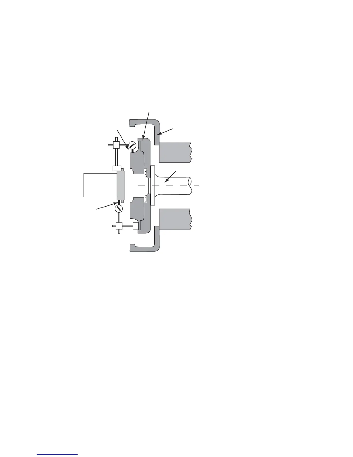
Mount a dial indicator on the fl ywheel coupling to the face of the
generator half coupling for angular alignment as shown in Figure 7.
Align the engine by rotating the prime mover in 90-degree incre ments
and measuring total indicator runout. Tighten the generator to the base
before taking each set of readings. Raise or lower the generator by
adding or removing shims under the machined feet.
Following the fi nal generator adjustment and runout check, remove
the horizontal shims from the adaptor fl ywheel housing, and move the
generator all the way to the adaptor. Then tighten the fasteners.
Recheck alignment. Make sure angularity (face) total indicated runout
does not exceed 0.005 inch per inch of generator coupling diameter and
parallel (radial) total indicated runout does not exceed 0.005” TIR.
Torque the fasteners to the value shown in Table 3.
Shaft
Flywheel housing
Dial indicator pointer
for angular alignment
Dial indicator pointer
for parallel alignment
Flywheel
Figure 7: Alignment check
IMPORTANT: Clearances between the
adaptor pilot and the fl ywheel housing
recess are designed to meet the tolerance
of 0.001 to 0.015 inches.