Page 7
Copyright © 2012 Kato Engineering, Inc. All rights reserved
Optional PMG system
The permanent magnet generator (PMG) system consists of the PMG
stator and PMG rotor:
The PMG stator is a stationary armature and is located within the stator
assembly that also contains the exciter stator or is a separate stator
mounted next to the exciter stator. The PMG stator consists of steel
laminations. The laminations are held in place by steel compression rings
and are welded to the frame bars of the exciter-PMG frame. The PMG
windings are placed in slots in the laminations. Insulating wedges are
inserted at the top of each slot to hold the coils in position.
The PMG rotor consists of rectangular permanent magnets and cast pole
tips secured to a steel hub with nonmagnetic stainless steel bolts. The
PMG rotor is keyed to the shaft and secured with a nut and lock washer.
PMG system overview: The PMG system functions as a pilot exciter,
providing power to the automatic voltage regulator power supply. The
PMG is an AC generator that uses permanent magnets in the rotor instead
of electromagnets to provide the magnetic fi eld (see Figure 1).
Other options
Other options include, but are not limited to, space heaters, fi lters, and
temperature sensing devices.
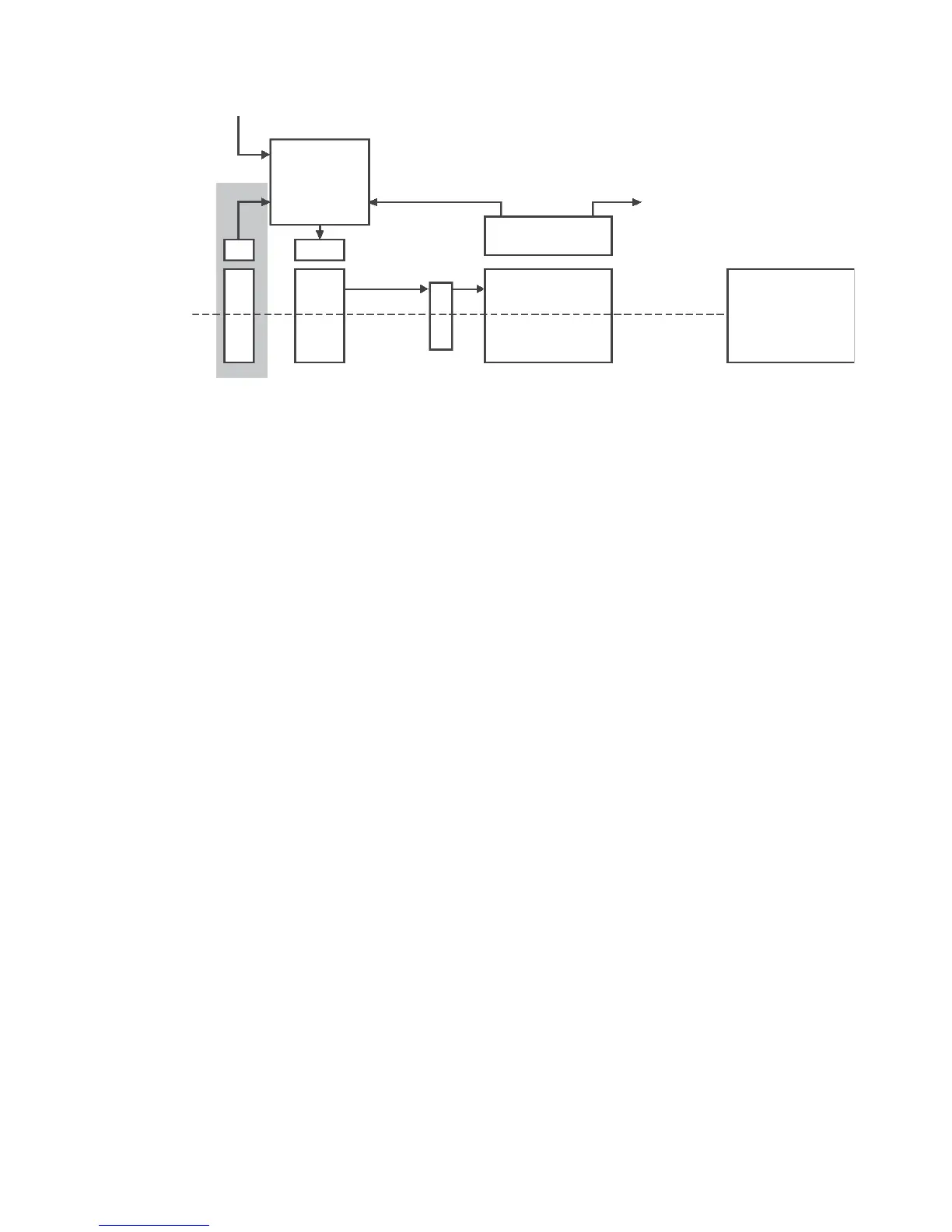
Figure 1: Overview of excitation system
(with an optional PMG)
Output leads
Voltage
regulator
Exciter stato
r
(fi eld)
Main stator
(armature)
Shaft
Main rotor (DC)
Rectifi er
Exciter
armature (AC)
PMG stato
r
(armature)
PMG rotor
(fi eld)
Prime mover
Power input