Page 19
Copyright © 2012 Kato Engineering, Inc. All rights reserved
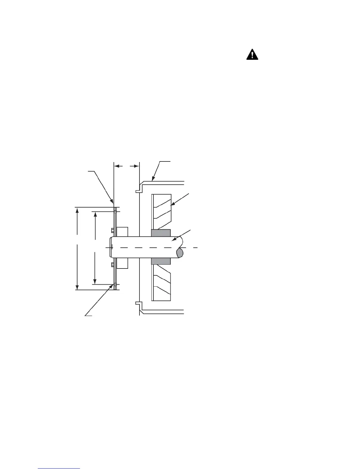
Measure the axial distance from the surface on the generator adapter
to the outside surface on the drive disc coupling plates (dimension Y
in Figure 14). This dimension is recorded on the Factory Recorded
Dimensions sheet, which was packaged with the generator. If the
dimensions do not match, move the rotor axially relative to the stator
until the dimensions are equal.
Measure the axial distance from the machined surface on the engine
fl ywheel housing the bottom of the fl ywheel drive disc recess
(dimension G in Figure 15). Make sure the difference between
dimensions Y (of Figure 14) and G are less than 1/32 inch. If G is
more than Y, install additional spacers between the drive discs and the
generator hub. If Y is more than G, remove spacers between the drive
discs and generator hub.
Figure 14: Single bearing generator drive plate
and adaptor
S
Y
W
A
Adaptor
Bolt holes
Drive
plates
Fan
Shaft
WARNING: Never grind the OD
of drive discs or attempt to drill out the
holes. If the dive discs do not fi t properly,
use different discs or a different fl ywheel.
The number and thickness of drive discs
are specifi ed for torque requirements. Do
not remove drive discs to compensate
for spacing Drive disc modifi cations may
result in drive disc failure and debris
ejected from the generator.