Page 22
Copyright © 2012 Kato Engineering, Inc. All rights reserved
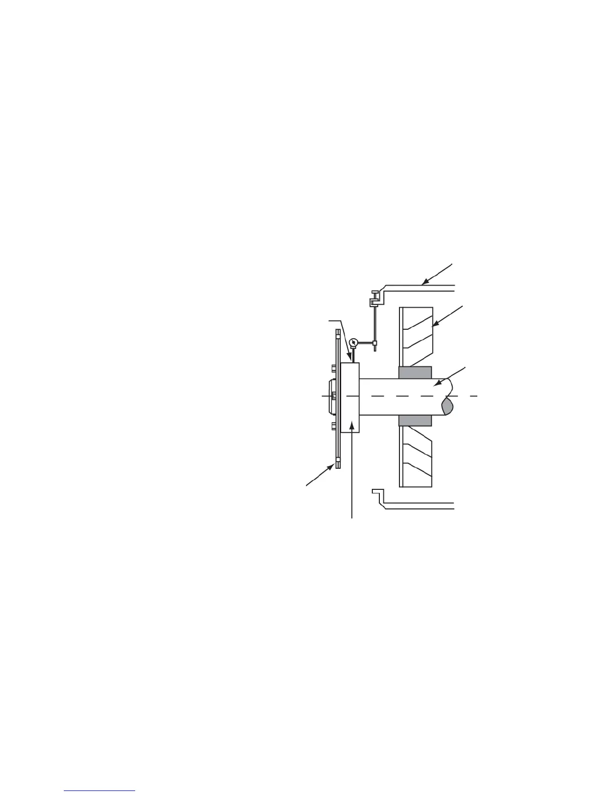
After installing the drive disc-to-fl ywheel bolts, check the runout of the
generator shaft by placing the base of a dial indicator on the generator
frame and positioning of the probe on the shaft as shown in Figure 18.
If the total indicated runout exceeds 0.003 inch, remove the drive discs
bolts, and rotate the generator relative to the engine fl ywheel. Reinstall
the bolts, and check the runout again.
Recheck the shaft-end-to-bearing-housing distance (dimension A in
Figure 13).
Mount the brushless exciter armature assembly to the generator shaft
(as described in the assembly procedures below).
Figure 18 Runout check
Drive plates
Dial indicator pointer
Drive hub
Shaft
Fan
Adapter