ii
TABLE OF CONTENTS
Section Page
i. Simplified Setup and Operating Instructions ...................................1
ii. Safety Warning .........................................................1
I. General Information .....................................................2
II. Setting Mode of Drive (Speed or Torque Control) ...............................4
III. Setting Selectable Jumpers ...............................................5
IV. Mounting ..............................................................6
V. Wiring ................................................................6
VI. Fusing ...............................................................10
VII. Operation ............................................................10
VIII. Trimpot Adjustments ....................................................11
IX. Function Indicator Lamps ................................................13
X. Limited Warranty .......................................................20
TABLES
1. Electrical Ratings .......................................................2
2. General Performance Specifications .........................................2
3. Summary of Control Operation .............................................4
4. Terminal Block Wiring Information ..........................................7
5. Field Connections .......................................................7
6. Control State vs Relay Contact State .......................................10
7. Current Limit Timer Settings ..............................................13
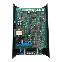
8. Parts List (Power Board) .................................................13
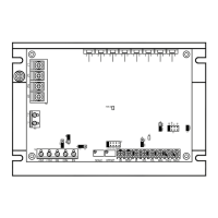
9. Parts List (Logic Board) ..............................................15, 16
FIGURES
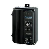
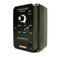
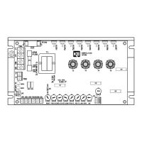
1. Control Layout .........................................................3
2A. Linear Torque Curve .....................................................5
2B. Non-Linear Torque Curve .................................................5
3. AC Line and Armature Connection ..........................................7
4A. Full Voltage Field .......................................................7
4B. Half Voltage Field .......................................................7
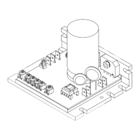
5. Mechanical Specifications .................................................8
6. Main Speed Potentiometer Connections ......................................9
7A. Voltage Following .......................................................9
7B. Enable ..............................................................10
7C. Start/Stop Circuit .......................................................10
7D. Alarm Contacts ........................................................10
7E. Tach-generator Connection. ..............................................10
8. Accel Trimpot Adjustment ................................................11
9. Offset Trimpot Adjustment ...............................................11
10. Deadband Trimpot Adjustment ............................................11
11. Power Board Schematic .................................................24
12. Logic Board Schematic ..................................................17
 Loading...