EasyManua.ls Logo

KB Electronics KBRG-212D User Manual

KB Electronics KBRG-212D
17 pages
To Next Page IconTo Next Page
Page #1 background imageLoading...
Page #1 background image
© 1997 KB Electronics, Inc.
INSTALLATION AND OPERATING INSTRUCTIONS
REGENERATIVE DRIVE
MODEL KBRG-212D
KB Part No. 8819
VARIABLE SPEED SCR CONTROL
DESIGNED FOR SHUNT WOUND
and PM DC MOTORS
FULL WAVE • 4 QUADRANT
See Safety Warning on Page 2
The information contained in this manual is intended to be accurate. However, the manufacturer
retains the right to make changes in design which may not be included herein.
See Page 2
A COMPLETE LINE OF MOTOR DRIVES
!
Question and Answer IconNeed help?

Do you have a question about the KB Electronics KBRG-212D and is the answer not in the manual?

KB Electronics KBRG-212D Specifications

General IconGeneral
Input Voltage115/230 VAC
Output Current12 Amps DC
Speed Range50:1
Enclosure TypeNEMA 1
Regulation1%
Power Rating2 HP
Output Voltage0-90 VDC @ 115 VAC input, 0-180 VDC @ 230 VAC input

Summary

Simplified Operating Instructions

Core Setup and Connections

Covers AC line/motor connections, speed/torque mode, motor current, enable circuit, and fuse.

Trimpot Settings Overview

Notes factory settings for trimpots.

Safety Warnings

General Information

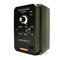
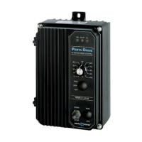
Overview of the KBRG-212D's capabilities and application.

General Information and Operation

Operation Overview

Explains speed and torque control in four quadrants.

Input Voltage and Current Jumpers

J1, J2 – Input AC Line Voltage Selection

How to set jumpers for correct AC line voltage input.

J3 – Armature Current Setting

Setting jumper J3 for motor current rating.

J4 – Motor Armature Voltage and Tach-Generator

Setting J4 for armature voltage and tach-generator input.

Control Mode and Function Jumpers

J5 – Analog Input Voltage Configuration

Setting jumper J5 for potentiometer or analog signal input.

J6 – Control Mode Selection

Selecting between Speed (SPD) and Torque (TRQ) control modes.

J7 - Stop Function: Coast or Regenerate

Configuring the stop function using jumper J7.

Mounting Instructions

Mounting Guidelines

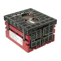
Instructions for physically installing the KBRG-212D.

Wiring Instructions

AC Line, Motor, Ground, and Field Connections

Detailed wiring instructions for AC line, motor, ground, and shunt field.

Control Layout

Control Board Layout Diagram

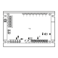
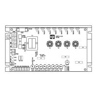
Diagram illustrating jumper and trimpot locations on the control board.

Mechanical Specifications

Physical Dimensions and Mounting

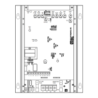
Provides physical dimensions, mounting details, and notes.

Speed Potentiometer and Voltage Following

Main Speed Potentiometer Connections

Details unidirectional and bidirectional potentiometer connections.

Voltage Following Connection

How to connect an analog signal for voltage following control.

Enable, Tach-Generator, and Fusing

Enable Start/Stop Circuits

Explains the electronic stop function using Enable terminals.

Tach-generator Feedback Integration

How to connect tach-generator for improved speed regulation.

Armature Fusing Guidelines

Information on armature fuse selection and types.

Acceleration, Deadband, and Response Trimpots

Acceleration/Deceleration Trimpots

Adjusting acceleration and deceleration times with FWD/REV ACCEL trimpots.

Deadband Trimpot Function and Adjustment

Explains and details setting the DB trimpot for control initiation and regeneration delay.

Current Limit, IR Comp, and Max Speed Trimpots

Forward and Reverse Current Limit (CL) Trimpots

Setting maximum DC current for forward and reverse motor directions.

IR Compensation Adjustment

Adjusting IR Comp for stable motor speed under varying loads.

Maximum Speed (MAX) Trimpot

Setting the maximum output voltage and motor speed using the MAX trimpot.

Function Indicator Lamps

Power On and Overload Indicators

Explains the Power On (PWR ON) and Overload (OL) indicator lamps.

Accessories

KBRG-212D Optional Accessories

Lists available optional accessories for the KBRG-212D.

Limited Warranty

Warranty Terms and Conditions

Details the warranty period, terms, and conditions for the product.

Related product manuals