11
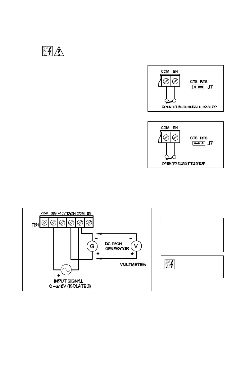
FIG. 13 – REGENERATE TO STOP
FIG. 14 – COAST TO STOP
G. Enable Start/Stop Circuits – The KBRG-212D contains a 2-wire stop circuit (Enable)
which is used to electronically bring the motor to a “stop.” An isolated single contact
closure is required. If an isolated contact is not available, it may be necessary to use an
isolation relay.
WARNING! Do not use Start/Stop or Enable functions as a safety
disconnect. Use only an AC line disconnect for that purpose.
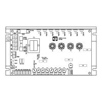
i. Regen to a stop using terminals EN and
COM on terminal block TB1 – When a
contact is opened between terminals “EN”
and “COM”, with jumper J7 in the “RTS”
position, the motor will regeneratively brake to
a stop. The braking time can be controlled by
adjusting the REV ACC trimpot when the
motor is in the forward direction and the FWD
ACC trimpot when the motor is in the reverse
direction. See fig. 13.
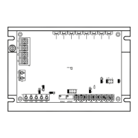
ii. Coast to a stop using terminals “EN” and
“COM” on terminal block TB1 – If coast to
stop operation is required, move jumper J7 to
the coast to stop (CTS) position. When the
contact is opened between “EN” and “COM,”
the motor will coast to a stop. See fig. 14.
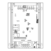
H. Tach-generator Feedback – The KBRG-212D is
factory set for armature feedback which provides
good load regulation for most applications. For
superior load regulation analog tach-generator
feedback can be used.
Wire the tach-generator so that the polarity of the tach-generator is the same with respect
to the input signal polarity (see fig. 15). Note: If tach-generator is wired with reverse
polarity, the motor will run at full speed.
FIG. 15 – TACH-GENERATOR FEEDBACK
NOTE: Check tach volt-
age polarity with respect to
input signal if polarity does
not match reverse tach
leads.
Be sure AC line is
disconnected when
rewiring tach-generator.
VI. FUSING.
Armature Fuse – An armature fuse (F1) rated 12A is provided with a rating equal to the
maximum RMS rating of the control. It is recommended that the correct size armature fuse
be installed, depending on the rating of the motor and form factor (RMS/AVG current). Fuse
type should be Littlefuse 326 ceramic or Buss ABC, or equivalent. A fuse chart is presented
below which suggests appropriate armature fuse ratings. However, the specific application
may require larger fuse ratings based on ambient temperature, CL set point and duty cycle
of operation (see table 8, p. 12). Fuses may be purchased from your distributor.