ii
TABLE OF CONTENTS
Section Page
i. KBRG-212D Simplified Operating Instructions .................................1
ii. Safety Warning .........................................................2
I. General Information .....................................................2
II. Operation .............................................................2
III. Setting Selectable Jumpers ...............................................3
IV. Mounting ..............................................................6
V. Wiring ................................................................6
VI. Fusing ...............................................................11
VII. Trimpot Adjustments ....................................................12
VIII. Function Indicator Lamps ................................................14
IX. Limited Warranty .......................................................18
TABLES
1. Electrical Ratings .......................................................2
2. Summary of Control Operation .............................................3
3. General Performance Specifications .........................................3
4. Jumper J3 Position vs Motor Horsepower .....................................4
5. Relationship of AC Line Input and Motor Voltage with J1, J2 and J4 Positions .........4
6. Terminal Block Wiring Information ..........................................6
7. Field Connections (Shunt Wound Motors Only) ................................7
8. Armature Fuse Chart ...................................................12
9. Parts List .........................................................15, 16
FIGURES
1. AC Line Voltage Jumper Setting ............................................4
2. Motor Armature Voltage Jumper Setting ......................................4
3. Jumper J5 Setting .......................................................5
4. Speed Control Mode .....................................................5
5. Torque Control Mode ....................................................6
6. AC Line and Armature Connection ..........................................7
7A. Full Voltage Field .......................................................7
7B. Half Voltage Field .......................................................7
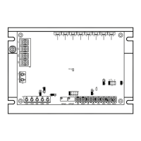
8. Control Layout .........................................................8
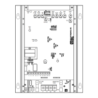
9. Mechanical Specifications .................................................9
10. Main Speed Potentiometer Connections (Unidirectional) .........................10
11. Main Speed Potentiometer Connections (Bidirectional) ..........................10
12. Voltage Following Connection .............................................10
13. Regenerate to Stop .....................................................11
14. Coast to Stop .........................................................11
15. Tach-generator Feedback ................................................11
16. Accel Trimpot Adjustment ................................................12
17. Deadband Trimpot Adjustment ............................................12
18. Schematic ............................................................17