S
samantha90Aug 3, 2025
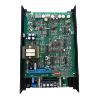
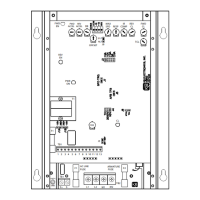
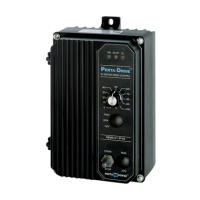
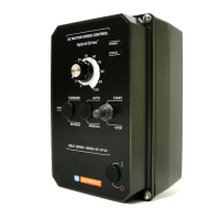
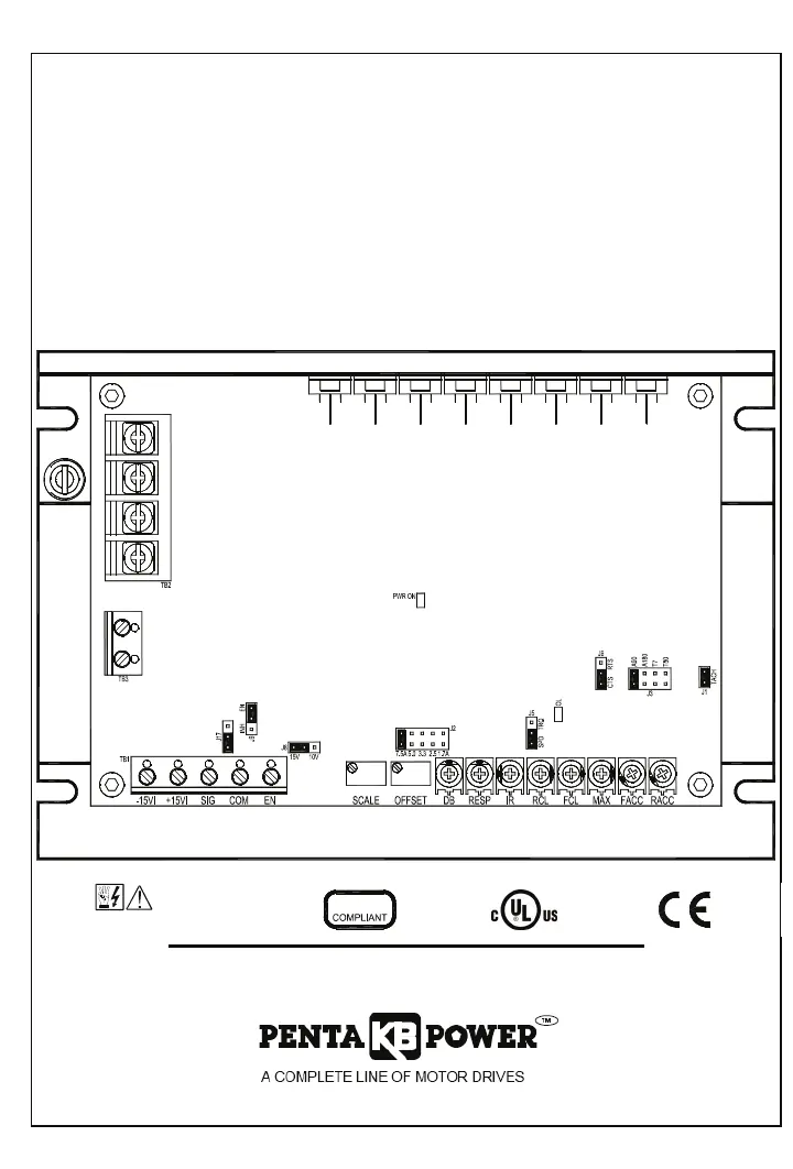
What to do if my KB Electronics DC Drives motor is not running but the LED is on?
- WWilliam ThompsonAug 3, 2025
If the motor of your KB Electronics DC Drive isn't running but the Power On LED is lit, the main speed potentiometer might be set to zero. Try adjusting the main speed potentiometer to your desired speed. Also, make sure the main speed potentiometer, signal input, and motor connections are all properly connected.