2
TABLE OF CONTENTS
Section
Page
1 Quick-Start Instructions.........................................................................4
2 Safety Warning ..................................................................................... 5
3 Introduction ...........................................................................................6
4 Important Application Information .........................................................12
5 Mounting Instructions ............................................................................ 12
6 Electrical Connections...........................................................................13
7 Setting Selectable Jumpers / Connector............................................... 19
8 Recommended High Voltage Dielectric Withstand Testing (Hi-Pot) .....23
9 Drive Operation ..................................................................................... 24
10 Trimpot Adjustments ............................................................................. 25
11 Diagnostic LED’s................................................................................... 30
12 Troubleshooting ....................................................................................30
Limited Warranty ..................................................................... Back Cover
Table Page
1 Standard Features ................................................................................ 7
2 Selectable Jumpers............................................................................... 7
3 Trimpot Adjustments ............................................................................. 8
4 Electrical Ratings ..................................................................................9
5 General Performance Specifications..................................................... 9
6 Terminal Block Wiring Information ........................................................ 13
7 Armature Fuse Chart............................................................................. 14
8 Field Connection ................................................................................... 15
9 Jumper J2 Setting vs. Motor Horsepower ............................................. 19
10 Summary of Control (Regen) Operation ...............................................25
11 Troubleshooting Guide..........................................................................30
Figure Page
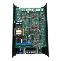
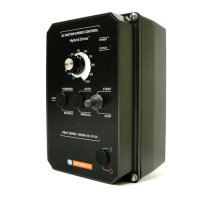
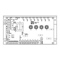
1 Control Layout............................................. .........................................10
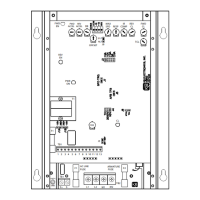
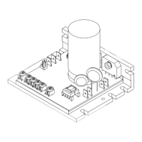
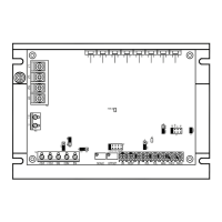
2 Mechanical Specifications........................... ......................................... 11
3 AC Line and Armature Connection ............. .........................................14
4 Full Voltage Field ........................................ .........................................15
5 Half Voltage Field........................................ .........................................15
6A Unidirectional Operation (Forward) ............. ......................................... 16
6B Unidirectional Operation (Reverse)............. .........................................16
6C Bidirectional Operation Reversing Contact . ......................................... 16
6D Bidirectional with Potentiometer.................. ......................................... 16
7A Voltage Following........................................ .........................................17
7B Current Following ........................................ ......................................... 17
7C J17 Voltage Scale ....................................... ......................................... 18
7D J8 Current Scale ......................................... ......................................... 18
8A Enable Mode ............................................... ......................................... 18
8B Inhibit Mode................................................. ......................................... 18
9 J1 Tach-Generator Connection................... ......................................... 19
10 J2 Armature Current Jumper ...................... .........................................19
11A J3 Armature Voltage (90V).......................... ......................................... 20
11B J3 Armature Voltage (180V)........................ ......................................... 20
12 J5 Speed /Torque........................................ ......................................... 20
13 Speed Mode vs. Motor Load ....................... ......................................... 20
14 Motor Speed vs. Applied Motor Load (Torque Mode) ........................... 21
15 J6 CTS / RTS Jumper................................. .......................................2