4
B. J3 – Armature Current – Select the J3 position (1.7, 2.5, 3.3, 5, 7.5) closest to the rated
motor current. (Note the maximum output current is set to 150% of the J3 position, which
may be readjusted using the FWD CL and REV CL trimpots.)
TABLE 4 – JUMPER J3 POSITION vs MOTOR HORSEPOWER
Jumper J3 Position
Motor Current
(DC Amps)
Motor Horsepower
90VDC 180VDC
7.5A 3/4 1
5.0A
2.5A
1.7A
3.3A
7.5A
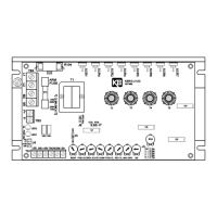
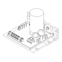
J3
5.0A 1/2 1
3.3A 1/3 3/4
2.5A 1/4 1/2
1.7A 1/6 1/3
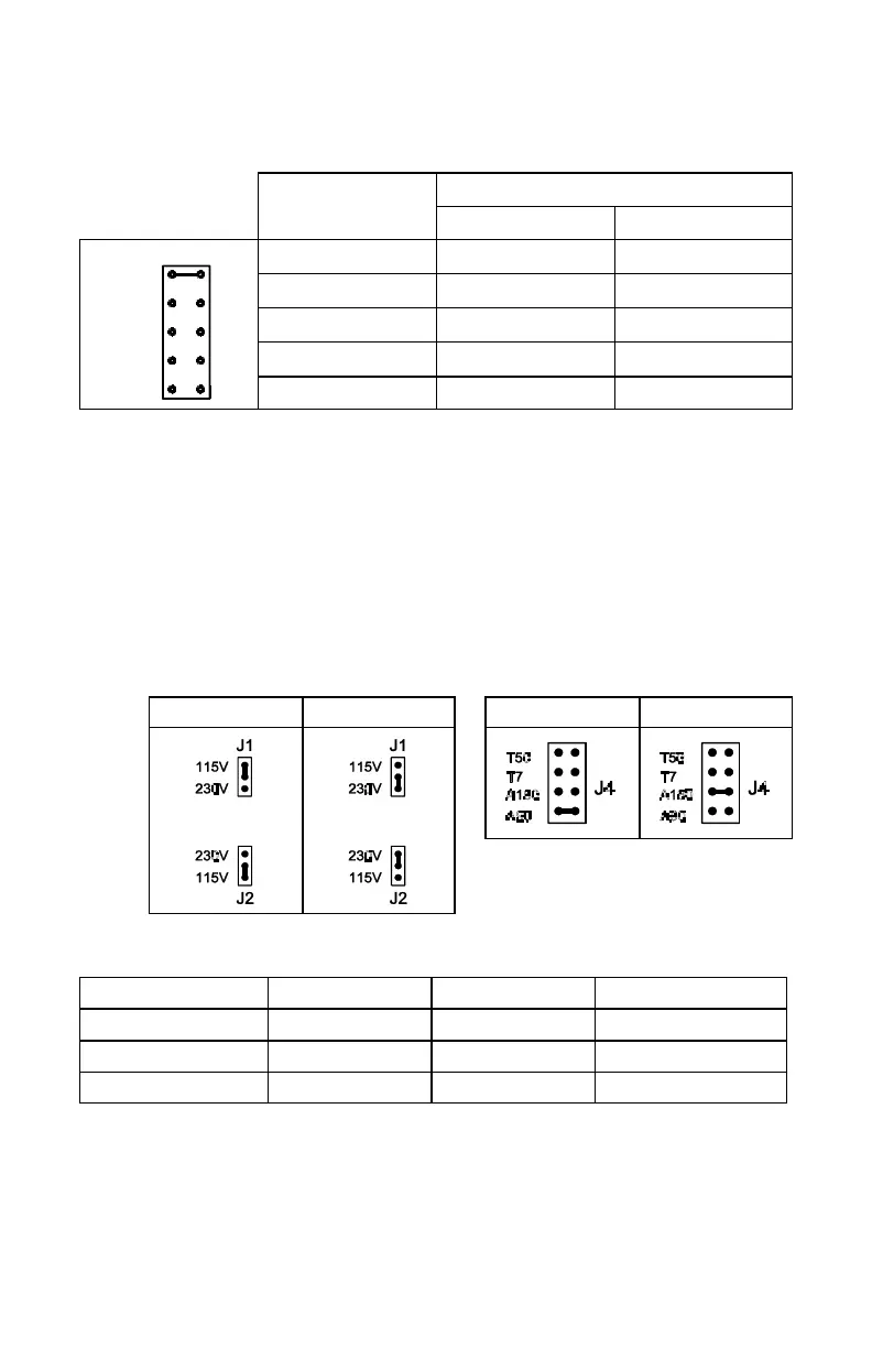
C. J4 – Motor Armature Voltage – Select the desired armature voltage by placing J4 in the
proper position, “A90" or “A180.” Note: For 115 volt AC Line input, the armature
voltage must be set to “90.” For 230 input, the armature voltage is normally set for
“180.” However, it is also possible to set the armature voltage to “90" for step-down
operation. (See fig. 2 and table 5.) Note: Jumper J4 is also used if tach-generator
feedback is to be used. (See fig. 2)
If a 7 volt per 1000 RPM tach-generator is used, place jumper J4 into the “T7" position.
For a 50 volt per 1000 RPM tach-generator, place the jumper into the “T50" position.
Note: When using tach-generator feedback, the IR Comp trimpot should be turned to a
minimum setting (full CCW).
FIG. 1 – AC LINE VOLTAGE
JUMPER SETTING
FIG. 2 – MOTOR ARMATURE
VOLTAGE JUMPER SETTING
115VAC 230VAC 90VDC 180VDC
TABLE 5 – RELATIONSHIP of AC LINE INPUT AND MOTOR
VOLTAGE with J1, J2 and J4 JUMPER POSITION
AC INPUT VOLTAGE J1, J2 POSITION J4 POSITION MOTOR VOLTAGE
115 115 90 90
230 230 180 180
230 230 90* 90*
*A 90VDC motor can be used with a 230VAC line. However, speed range may be reduced and
motor derating may be required.