12
FIG. 16 – ACCEL TRIMPOT ADJUSTMENT
FIG. 17 – DEADBAND TRIMPOT ADJUSTMENT
TABLE 8 – ARMATURE FUSE CHART
Motor Horsepower
Approx. DC Motor
Current Amps
Fuse Rating
(AC Amps)
90VDC 180VDC
1/8 1/4 1.3 2
1/6 1/3 1.7 2
1/4 1/2 2.5 4
1/3 3/4 3.3 5
1/2 1 5.0 8
3/4 1 7.5 12
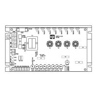
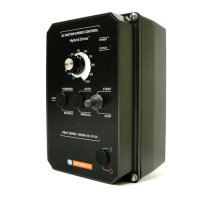
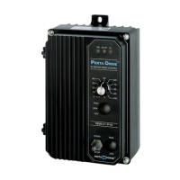
VII. TRIMPOT ADJUSTMENTS.
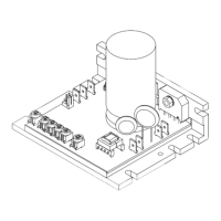
The KBRG-212D contains trimpots which have been factory adjusted for most applications.
See specifications for factory settings. (Note: Fig. 8 p. 8 presents the various trimpots with
their location. They are shown in the approximate adjustment position.) Some applications
may require readjustment of trimpots in order to tailor control to exact requirements. Readjust
trimpots as follows:
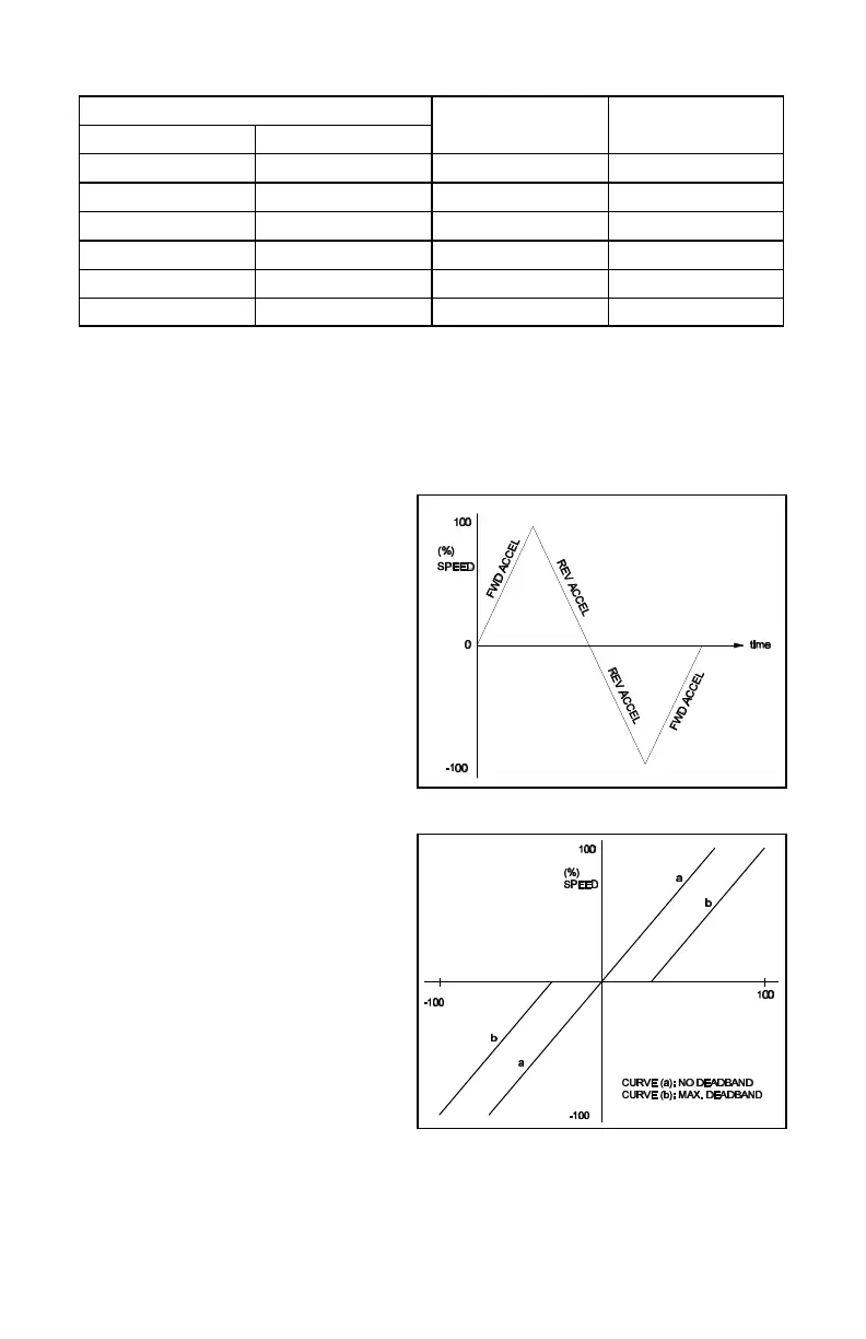
A. Forward Acceleration (FWD AC-
CEL) and Reverse Acceleration
(REV ACCEL) – The FWD ACCEL
trimpot determines the amount of
time it takes the control voltage to
reach full output in the forward di-
rection. It also determines the
amount of time it takes for the con-
trol voltage, in the reverse direc-
tion, to reach zero output. (FWD
ACCEL is the Reverse Decel.)
The REV ACCEL trimpot deter-
mines the amount of time it takes
the control voltage to reach full
output in the reverse direction and
the time it takes for the control volt-
age, in the forward direction, to
reach zero output. (REV ACCEL is
the Forward Decel.)
The FWD and REV ACCEL
trimpots are factory adjusted to
approximately 1 second. The ac-
celeration times are adjustable
over a range of 0.1 to 15 seconds.
See fig. 16 for graphical represen-
tation of ACCEL.
Note: The FWD and REV CL trim-
pots may override the rapid accel
and decel settings.
Note: A 4-quadrant
ACCEL/DECEL accessory module
(KB P/N 8803) is available as an
option. It provides separate con-
trol of FORWARD acceleration and
deceleration and REVERSE acceleration and deceleration.