33
APPENDIX A – Optional SIAC-PS Signal Isolator with Power Supply
See SIAC-PS Installation Instructions for details and connections.
Description
The SIAC-PS Signal Isolator with Power Supply provides an isolated interface between non-isolated signal sources
and the drive. It is used to isolate, amplify, and condition DC voltage and current signals from any source
(tach-generators, transducers, PLCs, and potentiometers). It provides an isolated input to control motor direction
and an isolated 5 Volt DC power supply for potentiometer operation. In addition, this updated model contains an
isolated 24 Volt DC power supply for transducers or auxiliary equipment. All input connections and power supplies
are isolated from the AC Line and motor wiring. It installs easily into the drive with a snap-in mounting base and is
wired with a connector.
Main features include voltage or current signal inputs. Other features include a power on LED, barrier terminal blocks
to facilitate wiring, multi-turn trimpots (MAX1, OFFSET), and a jumper for voltage or current signal input selection.
An optional accessory for use with the SIAC-PS is the Auto/Manual Switch to select a signal input from either the
SIAC-PS or the Main Speed Potentiometer of the drive.
Table 1 – General Performance Specications
Parameter Specication Factory Setting
Maximum Speed Trimpot (MAX1) Input Voltage Range (Volts DC) 0 to 2.5 thru 0 to 25 0 to 5
Offset Trimpot (OFFSET) Range (% of MAX1 Trimpot Setting) 0 – ±50 0
Input Current Range (milliamps DC) 4 – 20 —
Forward and Reverse Input Switch Types Dry Contact or Open Collector —
5 Volt DC Power Supply Maximum Load Current Rating (milliamps DC) 1 —
24 Volt DC Power Supply Maximum Load Current Rating (milliamps DC) 50 —
Potentiometer Operation (kΩ) 5 —
Input/Output Linearity (%) 0.1 —
Thermal Drift (millivolts per °C) 0.4 —
Operating Temperature Range (°C / °F) 0 – 40 / 32 – 104 —
Operating Humidity Range (% Relative, Non-Condensing) 0 – 95 —
Storage Temperature (°C / °F) -25 – +85 / -13 – +185 —
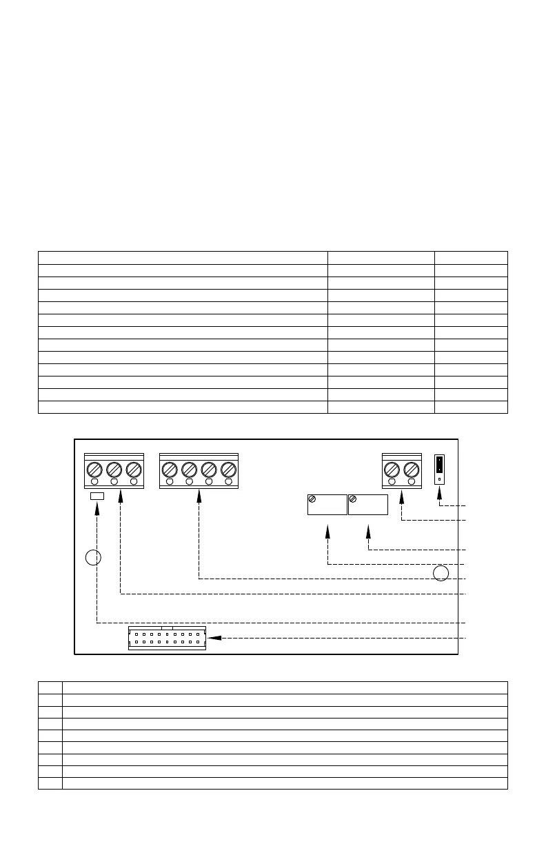
Figure 1 – SIAC-PS Layout and Descriptions*
CON1
OFFSET
TB1B
J1
PWR
CUR VOLT
+5V -5V OV FWD REV SIG1 COM1
MAX1
TB2
24V COM4
No. Description
1
J1: Sets the drive for operation with a voltage or current signal input.
2
TB2: Isolated 24 Volt DC power supply. Used for powering transducers or auxiliary equipment.
3
MAX1: Maximum signal input adjustment trimpot.
4
OFFSET: Signal Oset adjustment trimpot.
5
TB1B: Potentiometer or Signal Input and Direction Switch connections.
6
TB1A: Isolated 5 Volt DC power supply. Can be used for Main Speed Potentiometer operation.
7
PWR: Power On LED.
8
CON1: Used for the Ribbon Cable to connect the SIAC-PS to the drive.
*Layout may vary.
 Loading...