Q.1.20 February 2016
Page 3
© Copyright 2016 KE2 Therm Solutions, Inc., Washington, Missouri 63090
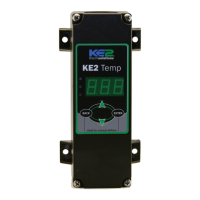
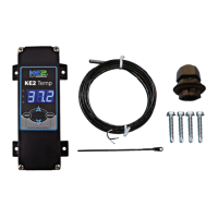
KE2 Temp + Defrost (pn 20611)
For Medium Temperature Applications with Air Defrost
Installation Manual
5 5
6
7
Replace high voltage shield after wiring is
completed.
The liquid line solenoid/compressor relay ac-
cepts a variety of input voltages and is not re-
quired to match the controller’s input. See table
for relay ratings. The relay uses the 3-position
screw terminal to make the connection on the
board. This relay is designed to control smaller
compressors directly. It may also control either
the liquid line solenoid or as a pilot to the com-
pressor contactor.When connecting the wires to
the relay, the controller will be breaking one leg
of the power.
One leg of incoming power (L1) supply for the
liquid line solenoid should be connected to the
common terminal of the liquid line solenoid
relay, the right most terminal connection. The
other leg of the incoming power (L2) should be
connected directly to the solenoid lead. The re-
maining lead from the solenoid should be con-
nected to the NO (normally open) terminal, the
leftmost terminal location.
Proper wiring practices must be followed. Local
wiring codes take precedence over any informa-
tion in this bulletin.
6
Connect line (L1) to the right terminal position
and neutral (L2) to the left terminal position.
Voltage Table
Outputs:
(1) Relay
Single Pole Double
Throw
Normally Open Normally Closed
120V 240V 120V 240V
FLA 30A 30A N/A 10A
LRA 98A 80A N/A 20A
Resistive N/A 30A N/A 30A
Horsepower 1 hp 2 hp 1/4 hp 1/2 hp
Pilot Duty 800VA 720VA 290VA 360VA
 Loading...