EasyManua.ls Logo

KE2 AdaptiveControl - User Manual

KE2 AdaptiveControl
20 pages
Print Icon
To Next Page IconTo Next Page
Loading...
Parts List
The following parts are included in the KE2 Adaptive Control
controller kits:
Kit # 21177 with 120/208-240 VAC controller
(1) KE2 Adaptive Control controller
(1) high voltage safety shield
(1) 3-pack of colored 15’ temperature sensors
(6) 90° spade connectors
(2) straight spade connectors
(5) self-tapping screws
(2) 1/2” plastic knockout plug
(1) air sensor mount
(3) course thread screws
(1) KE2 Terminal Board*
(1) Warranty card
(not shown)
© Copyright 2016 KE2 Therm Solutions, Inc., Washington, Missouri 63090
Q.1.35
January 2016
KE2 AdaptiveControl (pn 21177)
Quick Start Guide
Supplies List
The KE2 Adaptive Control is supplied with all of the accessories re-
quired for the controller to work, however, standard truck stock items
will also be required to install the controller. To simplify the installa-
tion, a list of items has been provided.
Conduit to go between the controller and the evaporator
(2) Conduit connectors (straight or elbow as required)
(8) High voltage wires matched to the load of the heaters,
fans, liquid line solenoid, and the controller.
(8) Spade Connectors matched to the gauge of high volt-
age wires
Wire labeling (numbers, colors, etc.)
Wire ties
18 gauge twisted shielded pair (if extending sensor wires)
Foam insulation if running wires outside the space.
Silicone (for sealing any box penetrations)
Accessories to Aid in Installation
The following parts are available separately:
10’ Wire Harness pn 20736, 25’ Wire Harness pn 20670, or 40’ Wire
Harness pn 20737
Further information on the Wire Harness can be found in literature
Q.1.21.
* When used with the KE2 Adaptive Control controller, the fuses must be sized to
match the application (i.e. Replace existing fuses with 30 Amp Time Delay fuses
for fans and compressor)
D E F
G
H
B
C
A
I
J
This reference should remain on site with the installed KE2 Adaptive Control controller.
A
C
D
E
F
G
H
I
B
J
Question and Answer IconNeed help?

Do you have a question about the KE2 AdaptiveControl and is the answer not in the manual?

KE2 AdaptiveControl Specifications

General IconGeneral
BrandKE2
ModelAdaptiveControl
CategoryController
LanguageEnglish

Summary

Coil Sensor Location Determination

Identifying the Coldest Spot for Sensor Placement

Steps A-D to find the optimal location where frost disappears last.

Mounting the Coil Sensor

Guidance on physically installing the sensor, including using plugs and considerations.

Controller Installation Site Selection

Determining Controller Placement Options

Discusses various locations for controller installation and environmental considerations.

Conduit and Wire Length Measurement

Steps for measuring conduit length and determining necessary wire lengths.

Controller Power and Conduit Preparation

Determining Unit Current Draw and Conduit Feeding

Checking unit nameplate for amp rating and preparing conduit for wires.

Connecting Controller Power and Voltage Selection

Wiring controller power and setting the voltage selector switch for correct operation.

Wiring Control Relays

Liquid Line Solenoid;Compressor Relay Wiring

Instructions for wiring the Liquid Line Solenoid/Compressor Relay.

Defrost and Fan Relay Wiring

Steps for wiring the Defrost (Heater) Relay and the Fan Relay.

Finalizing Controller and Evaporator Connections

Installing Controller Safety Cover and Sensor Wires

Mounting the controller's safety cover and connecting sensor wires.

Preparing Evaporator for Conduit Connection

Steps for accessing the evaporator's terminal block and connecting conduit.

Evaporator Wiring - Fans and Power

Removing Existing Wiring and Connecting Power

Removing old wiring and connecting controller power to line power.

Connecting Evaporator Fan Control Wires

Wiring instructions for controlling evaporator fans via the KE2 Adaptive Control.

Evaporator Wiring - Heaters and Solenoid

Connecting Evaporator Heater Control Wires

Connecting the evaporator heater control wires to the controller.

Connecting Liquid Line Solenoid Control Wires

Connecting the liquid line solenoid control wires to the controller.

Sensor Installation Details

Labeling and Installing Air Sensors

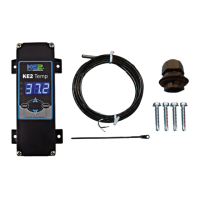
Guidance on labeling sensors and installing the air sensor bracket assembly.

Air Sensor Bracket Mounting Procedures

Specifics on mounting the air sensor using the provided bracket and screws.

Advanced Coil Sensor Installation Techniques

Proper Coil Sensor Installation Methods

Explains two methods for installing the coil sensor for optimal defrost termination.

Extending Sensor Wires Safely

Guidelines for extending sensor wires, avoiding interference from high voltage.

Final Controller Installation Steps

Setting Buzzer and Mounting the Controller

Configuring the on-board buzzer and physically mounting the controller unit.

Leaving Installation Instructions Onsite

Recommends leaving installation instructions at the site for future service.

Controller Navigation and Menu Structure

Understanding Controller Indicators and Basic Navigation

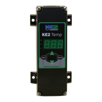
Explains controller indicator lights and basic navigation using the 4-button interface.

Accessing Controller Menus

Guides users on entering and navigating the controller's basic and advanced menus.

Controller Specifications and Key Operations

Overview of Controller Specifications

Details controller input voltage, temperature ranges, IP rating, and sensor specifications.

Manual Defrost and Setpoint Adjustment

Instructions for performing manual defrost and adjusting controller setpoints.

Controller Menu Parameters and Alarms

Alarm Codes and Basic Menu Setpoints

Lists controller alarm codes and parameters available in the basic menu.

Schedule Defrost Setpoints Overview

Details setpoints related to different scheduled defrost operations.

Advanced Controller Configuration Setpoints

Advanced Menu Setpoints Explained

Lists and describes parameters available in the advanced menu for detailed configuration.

Defrost and Fan Control Setpoint Details

Specific setpoints for defrost initiation, time, and fan delay management.

Controller Variables and Abbreviations Reference

Non-Adjustable Variables Displayed on Controller

Explains variables displayed on the controller and their status meanings.

Alphabetical Listing of Controller Abbreviations

Comprehensive list of abbreviations used in controller menus and their descriptions.

Detailed Parameter Definitions

Alarm and System State Parameter Definitions

Defines alarm codes and various system state parameters for user understanding.

Setpoint and Variable Parameter Definitions

Provides detailed definitions for setpoints, variables, and input types.

Custom Defrost Setup Guide

Step-by-Step Custom Defrost Configuration

Detailed guide on how to set up custom defrost schedules for the controller.

Related product manuals