© Copyright 2019 KE2 Therm Solutions, Inc., Washington, Missouri 63090
Q.3.65
June 2019
KE2 Temp + Air Defrost (pn 20611)
For Medium Temperature Applications with Air Defrost
Condensed Quick Start Guide
Supplies List
The accessories required for the controller to work are supplied.
However, some truck stock items may be needed. See the following list.
conduit to go between the controller & evaporator
(2) conduit connectors (straight or elbow as required)
(4) high voltage wires (matched to the load of the liquid line solenoid/
compressor and the controller.)
This reference should remain on site with the installed controller.
Programming
Press & hold ENTER button
to access setpoint menu
Use arrow buttons to
select function:
tS = Temperature Setpoint
diF =
CSH = Max Compressor
Starts/ Hour
dPd = Defrost Per Day
dFt = Defrost Time
LAO =
tAd = Temp Alarm Delay
Adr = Mod Bus Address
Unt = Units for temp display
Press ENTER & use arrows
to change value
Press & hold ENTER button
Alarms
When amber LED is lit:
SSA = Shorted Sensor Alarm
OSA = Open Sensor Alarm
HtA = High Temp Alarm
LtA = Low Temp Alarm
pn 20679 06/14
B
C
D
E
F
A
G
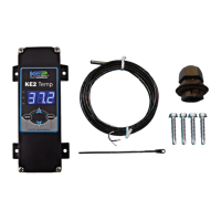
What’s in the Kit
The following parts are included:
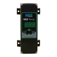
(1) KE2 Temp + Air Defrost controller
(1) temperature sensor - 45”
(1) sensor ziptie
(1) liquid tight cord grip
(4) self-tapping mounting screws
(2) screws for high voltage shield
(1) programming sticker
A
C
D
E
B
F
G
Use the up and down arrows to scroll through available setpoints.
Access Setpoint mode by pressing and holding the button
until tS (temperature setpoint) displays on the screen
ENTER
ENTER
Press to view the current setting.
tS = Temperature Setpoint
diF = Dierential
CSH = Maximum Compressor Starts/Hour
dPd = Defrost Per Day
dFt = Defrost Time
HAO = High Alarm Oset
LAO = Low Alarm Oset
tAd = Temp Alarm Delay
Adr = Mod Bus Address
Unt = Units for temp display (FAH or CEL)
Setpoints
Use the up and to change the setpoint
ENTER
Press to move between the digits to accelerate the changes.
ENTER
Press and hold to conrm each setpoint change
BACK
Press to escape.
Only visible if
CUS (custom) is
selected for dPd
(Defrost per day)
Alarms - When amber LED is lit:
SSA = Shorted Sensor Alarm
OSA = Open Sensor Alarm
HtA = High Temp Alarm
LtA = Low Temp Alarm
Indicator
Lights:
Red blinking - Real Time Clock battery needs to be replaced
Yellow light - non-critical alarm (system running)
Green light - compressor on
Green blinking - compressor waiting on timer to start/stop
tOd
d1
d2
d3
d4
d5
d6
d7
d8
d9
d10
d11
d12
wire labeling (numbers, colors, etc.)
additional wire ties
18 gauge twisted shielded pair (if extending sensor wires)
Cat5e wire (if adding communication)
foam insulation (if running wires outside the space)
silicone (for sealing any box penetrations)
Controller Navigation
Complete Instructions
Please visit: http://ke2therm.com/product/ke2-temp-defrost/
and click the Link to Literature button
use this QR code.
KE2 Temp Literature
— OR —
KE2 Temp Videos
Basic Setpoints
Setpoint Description Minimum Default Maximum
tS Temperature Setpoint -50°F (-45°C) 35°F 100°F (38°C)
diF Dierential 1°F (1K) 2°F 30°F (17K)
CSH Max. Comp. Starts/Hr. 5 (O)* 6 10
dPd Defrost Per Day 0 6 12, CUS**
dFt Defrost Time 0 min 15 min 720 min
HAO High Alarm Oset 1°F (1K) 5°F 10°F (6K)
LAO Low Alarm Oset 1°F (1K) 3°F 10°F (6K)
tAd Temp Alarm Delay 1 min 90 min 180 min
Adr Mod Bus Address 1 1 247
Unt Units for temp display FAH FAH CEL
*Selecting fewer than 5 compressor starts per hour results in the starts per hour feature
being turned o. The compressor will then function on temperature only.
** Selecting CUS (custom) unlocks additional Setpoints. See Advanced Setpoints table.
For a complete list of setpoints and descriptions see Q.3.20.