Parts List
The following parts are included in the
KE2 Evaporator Eciency (KE2 Evap) controller kits:
Kit #20178 with 120/208-240 VAC controller
Kit #20844
with 120/208-240 VAC controller
Kit #20631
with 120/208-240 VAC controller
Kit #21096
with 120/208-240 VAC controller
Kit #20222
Beacon® I & II replacement controller
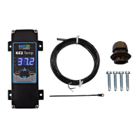
(1) KE2 Evaporator Eciency controller
(1) high voltage safety shield
(3) 10’ temperature sensors
(4) 90 degree quick disconnects
(5) self-tapping screws
(2) course thread screws (1) ne thread machine screw with
lock washer
(1) KE2 Terminal Board
(1) KE2 Evap Navigation sticker
(2) 1/2” plastic knockout plugs
(4) wire ties (rated for low temp)
(1) Air sensor mount
(1) 5-position screw down terminal (for EEV)
(4) 3-position screw down terminals (for power in, transducer
and 3A relay)
(9) 2-position screw down terminals (for sensors and digital
input, analog output)
1) 120 Voltage jumper
(1) 208-240V Voltage jumper (already on back of KE2 Evap)
© Copyright 2015 KE2 Therm Solutions, Inc., Washington, Missouri 63090
Q.1.3
July 2015
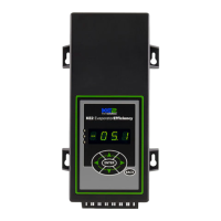
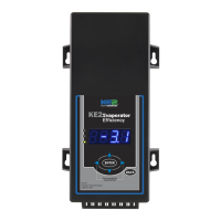
KE2 EvaporatorEfciency
Quick Start Guide
Supplies List
The KE2 Evap is supplied with all of the accessories required for the con-
troller to work, however, standard truck stock items will also be required
to install the controller. To simplify the installation, a list of items has
been provided.
Conduit to go between the controller and the evaporator
(2) Conduit connectors (straight or elbow as required)
(11) High voltage wires matched to the load of the heaters, fans,
liquid line solenoid, alarm (if used), and the controller.
(8) Spade Connectors matched to gauge of high voltage wires
Wire labeling (numbers, colors, etc.)
Additional wire ties
18 gauge twisted shielded pair (if extending sensor wires)
Foam insulation if running wires outside the space.
Silicone (for sealing any box penetrations)
Accessories to Aid in Installation
The following parts are available separately:
10’ Wire Harness pn 20736,
25’ Wire Harness pn 20670
40’ Wire Harness pn 20737
KE2 Evap Mounting Box pn 20687
Further information on the Wire Harness and Mounting Box can be found in
literature Q-1-21.
L M N
D
E
O
P
F
B
Left Arrow & Right Arrow
Use to move between Menus columns
Up Arrow & Down Arrow
Scroll through Menu Parameters
ENTER
Press and hold ENTER for 3 seconds, when
display is blinking changes can be made.
BACK
Press BACK to return to the previous view.
Press and hold ENTER for 3 seconds.
Change settings:
Save changes:
Moving through controller menus:
Return to Main Menu:
Lights:
Red - critical alarm (system not running)
Yellow - non-critical alarm (system running)
Green - compressor should be on
- compressor waiting on timer to start/stop
ENTER
Press ENTER to go from parameter to value.
Toggle beween
description & value :
Menu Layout:
Variables Manual*
(view only)
Alarms
(view only)
ENTER
Setpoints
Enter
Password
NO ALARM
EMAIL FAILURE
ROOM TEMP
DERIVATIVE
ROOM TEMP
FIRMWARE VERSION
MANUAL CONTROL
CLEAR MD
Controller Navigation
ENTER
ENTER
BACK
Press BACK 3 - 4 times
If you lose your place:
* For manual defrost use MANUAL CONTROL
BACK
24-hour Emergency Support: 1.888.337.3358 www.ke2therm.com
pn 21061 9-14
A
C
G H
I
J
K
This reference should remain on site with the installed KE2 Evaporator Eciency controller.
A
C
D
E
F
G
H
I
J
K
L
M
N
B
O
P
20844 KE2 Ultimate Install kit includes KE2 Mounting Box pn 20687 and 40’
colored temperature sensors
20631 kit does not include temperature sensors
21096 KE2 Supermarket Retrot kit also includes KE2 Mounting Box pn 20687,
10’ Wire Harness pn 20736, Ethernet Adaptor pn 20938, & Door Switch 20543
20222 Beacon® kit includes an extra temperature sensor, and pressure
transducer with cable.
Now with
Smart Access!
Get your controller
online in 3 easy steps.
See page16