© Copyright 2015 KE2 Therm Solutions, Inc., Washington, Missouri 63090
Q.1.3 July 2015
Page 13
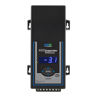
KE2 EvaporatorEfciency
Quick Start Guide
Specications
Controller
Input Voltage: 120V or 208 - 240V
Ambient Temp: -40° to 140°F
Operating Temp: -40° to 140°F
Display: 4-digit alphanumeric LED
IP Rating: IP65
Inputs:
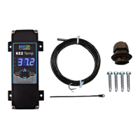
(4) temperature sensors (KE2 SKU 20200)
(1) pressure transducer (KE2 SKU 20204)
Valve Types: unipolar and bipolar stepper motors (12V) (Beacon® is 21V)
Relays:
20A resistive (defrost)
10A inductive (evaporator fan)
(2) 3A inductive rated cycles
Digital Input 1:
door contact, use 2nd air temp setpoint, disabled, system
o, external alarm notication
Digital Input 2:
door contact, use 2nd air temp setpoint, disabled, system
o, external alarm notication, defrost lockout, defrost
interlock
Digital Input 3:
door contact, use 2nd air temp setpoint, disabled, system
o, external alarm notication, lights
Communication: Standard TCP/IP
Pressure Transducer - pn 20201 (10 ft lead) or pn 20204 (40 ft lead)
Pressure Range: 0 to 150 psia
Proof Pressure: 450 psi
Burst Pressure: 1500 psi
Operating Temp: -40° to 275°F
Temperature Sensor
Sensor Specs: -60° to 150°F moisture resistant package
208-240
120
120
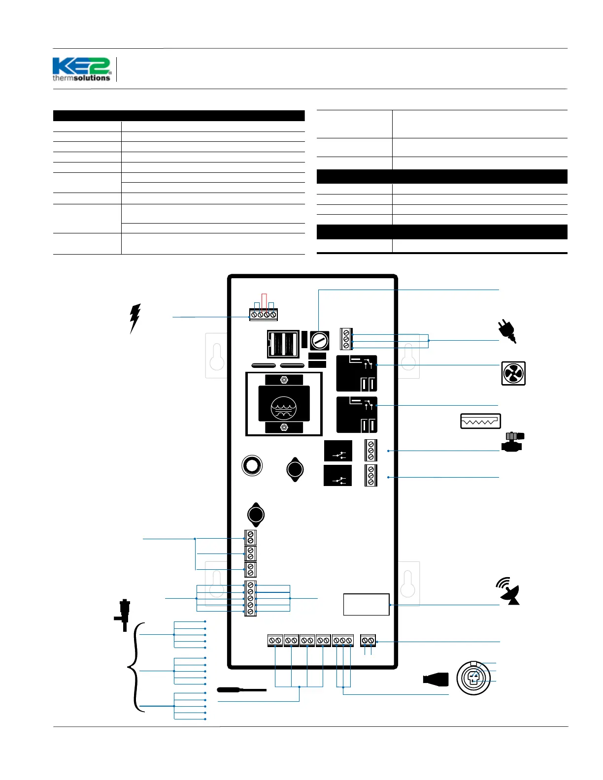
Temperature Sensors Pressure
Transducer
T1SuctT4Aux T2AirT3Coil
line / L1
ground
neutral / L2
NC
NO
NO NC
NO NC
COM
COM
NC
Power In
green
red
black
NO
Transformer
3A Relay
3A Relay
COM
COM
COM
NC
NO
COM
NC
NO
18V
DI 1
DI 3
DI 2
Electric Valve:
Temperature Sensors (4)
Pressure Transducer
RJ45 Ethernet Connection
DAC for ECM Fan
Fuse
empty
red
green
white
black
Auxiliary Relay
Fan Relay
(10 amp)
ground
signal
+5
Defrost (Heater) Relay
(20 amp)
1/2 or 500mA
Time Delay
Liquid Line Solenoid
Power In
(compressor)
door switch
system o
dual temp setting
external alarm
light switch
defrost interlock
defrost lockout
Digital Inputs
Pressure Transducer
Wiring Detail
black
red
green
Voltage
Selector
120V - Jumpers
1&2 3&4
208-240V Jumper
2&3 only
1 2 3 4
0-10V analog out
+
_
KE2 HSV KE2 RSV
blue
orange
yellow
red
black
yellow
blue
red
white
black
Beacon® I
blue
red
white
black
Beacon® II
brown
green
white
black
Beacon® II
Part Number
20222 Beacon
replacement
controller
required.
Wiring Diagram