A B
KE2 EvaporatorEfciency
Quick Start Guide
Q.1.3 July 2015
Page 12
© Copyright 2015 KE2 Therm Solutions, Inc., Washington, Missouri 63090
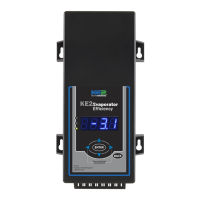
Alternate method - As the defrost termination sensor, it is important
to ensure the sensor does not terminate defrost before all frost has
been removed from the coil. In some installations, inserting the sen-
sor into the coil may position it too close to the defrost heat source.
An alternate method of positioning places the sensor vertically be-
tween the coil ns. This shows the coil sensor properly secured.
Extending sensor wires
After the sensors are mounted, they are routed back to the control-
ler. If the wires must be extended, use 18 gauge twisted shielded
pair. Maximum length for 18 gauge: 100ft.
When running the wires back to the controller care must be tak-
en to avoid interference being introduced into the sensor wires.
Interference can be introduced when sensor wires are located
near high voltage lines. High voltage is dened by Underwriter’s
Laboratories as above 30V. The higher voltage the more likely it is to
introduce interference, and the more important to avoid.
If crossing a high voltage line is necessary, the sensor wiring should
be run at right angles to prevent noise.
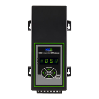
25
Figure 25A shows the sensor touching two circuit tubes. When in-
serting the sensor into the coil, the tip should touch one of the cir-
cuit tubes. It should not be located adjacent to the electric heating
elements. It should be about half the distance between the heat-
ers if possible. In Figure 25B the probe is inserted into the ns ap-
proximately 1/16” deeper than the stainless shielding. Pinch the ns
gently together, securing the sensor in place. This provides thermal
ballast to ensure a complete defrost.
25
26
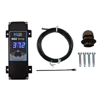
Connecting sensor wires to controller
The temperature sensors are designed to be attached to the con-
troller using 2 position screw terminals. Using a connector from the
accessory kit, attach the sensor to the screw terminal. The sensors are
not polarized, so wire location does not eect sensor performance.
Connect all sensors to a screw terminal.
Once connected, the sensors should be plugged into the proper lo-
cation on the controller. The location can be determined from the la-
bel on the interior wall of the enclosure or from the Wiring Schematic.
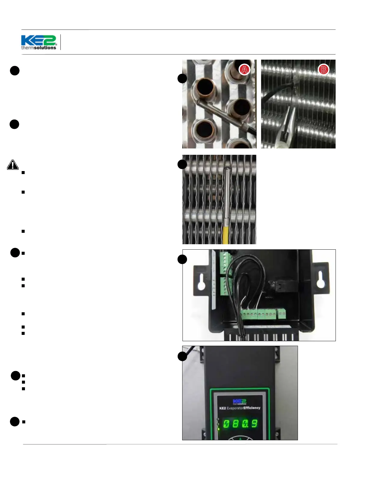
Strain relief
The enclosure is designed with a strain relief bar to prevent the sen-
sor wires from becoming unplugged from inadvertent contact.
Before securing the sensor wires, create a service loop. Figure 27.
Using a cable tie from the accessory kit, securely fasten the sensor
wires to the strain relief bar.
Note: Unused connectors should be placed (installed) in their re-
spective location for future use.
27
Controller Mounting
Locate the 4 stainless steel screws in the accessories kit
Install the 4 screws
Place the controller on the mounting screws and tighten down the
screws.
28
28
Final Step
Leave the installation instructions onsite in a convenient location,
where it can be easily located, for future service.
29
26
27
 Loading...