EasyManua.ls Logo

KE2 Temp + Defrost User Manual

KE2 Temp + Defrost
8 pages
To Next Page IconTo Next Page
Page #1 background imageLoading...
Page #1 background image
Programming
Press & hold ENTER button
to access setpoint menu
Use arrow buttons to
select function:
tS = Temperature Setpoint
diF =
CSH = Max Compressor
Starts/ Hour
dPd = Defrost Per Day
dFt = Defrost Time
LAO =
tAd = Temp Alarm Delay
Adr = Mod Bus Address
Unt = Units for temp display
Press ENTER & use arrows
to change value
Press & hold ENTER button
Alarms
When amber LED is lit:
SSA = Shorted Sensor Alarm
OSA = Open Sensor Alarm
HtA = High Temp Alarm
LtA = Low Temp Alarm
pn 20679 06/14
© Copyright 2016 KE2 Therm Solutions, Inc., Washington, Missouri 63090
Q.1.20
February 2016
KE2 Temp + Defrost (pn 20611)
For Medium Temperature Applications with Air Defrost
Installation Manual
Supplies List
All of the accessories required for the controller to work
are supplied, however, standard truck stock items are re-
quired to install the controller. A list is provided below:
conduit to go between the controller & evaporator
(2) conduit connectors (straight or elbow as required)
(4) high voltage wires matched to the load of the
liquid line solenoid/compressor and the controller.
wire labeling (numbers, colors, etc.)
additional wire ties
18 gauge twisted shielded pair (if extending sensor
wires/adding communication)
foam insulation (if running wires outside the space)
silicone (for sealing any box penetrations)
This reference should remain on site with the installed KE2 Temp + Defrost controller.
What’s in the Kit - Parts List
The following parts are included in the
KE2 Temp + Defrost kit:
(1) KE2 Temp + Defrost controller
(1) temperature sensor - 45”
(4) self-tapping mounting screws
(1) liquid tight cord grip
(1) sensor ziptie
(1) programming sticker
(2) screws for high voltage shield
B
C
D
E
F
Select Mounting Location
The KE2 Temp is designed for a wide range of applications; therefore
there are many potential installation locations. Breaking down the in-
stallation location by application provides the most helpful reference.
Application Locations
Undercounter Evaporator cabinet
Outside controlled space
Walk-in Evaporator cabinet
Adjacent to entrance
Side-by-side Above door
Walk-in Under Counter
CommercialWine Cabinet
A
F
A
C
D
E
B
F
G
Question and Answer IconNeed help?

Do you have a question about the KE2 Temp + Defrost and is the answer not in the manual?

KE2 Temp + Defrost Specifications

General IconGeneral
ModelKE2 Temp + Defrost
CategoryController
Temperature Control Range-40°F to 140°F (-40°C to 60°C)
Defrost ControlYes
Operating Temperature-40°F to 140°F (-40°C to 60°C)
Control TypeOn/Off
Output TypeRelay
CommunicationModbus RTU
Storage Temperature-40°F to 158°F (-40°C to 70°C)
Humidity0 to 95% RH, non-condensing
DisplayLED
Sensor TypeThermistor
Relay Contact Rating10A @ 240VAC
Defrost TerminationTime or Temperature

Summary

Kit Contents and Parts List

Required Supplies

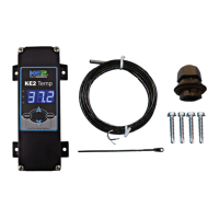
Lists accessories required for controller installation beyond kit components.

Mounting Location Guidance

Undercounter Application

Specifies mounting location for undercounter applications.

Walk-in Application

Specifies mounting location for walk-in applications.

Side-by-side Application

Specifies mounting location for side-by-side applications.

Controller Wiring Guide

Low Voltage Connections

Communication Setup

Details RS-485 Modbus communication setup and connections.

Controller Programming

Navigation and Setpoint Overview

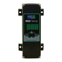
Explains interface navigation, button functions, and lists available setpoints.

Indicator Light Functions

Describes the meaning of the controller's indicator lights for alarms and status.

Setpoint Configurations

Advanced Setpoint Options

Details setpoints available when CUS (custom) is selected for defrosts per day.

Custom Defrost Configuration

Physical Dimensions

Wiring Diagram

Related product manuals