Q.1.3 July 2015
Page 5
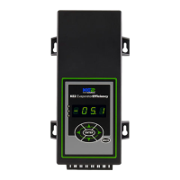
KE2 EvaporatorEfciency
Quick Start Guide
© Copyright 2015 KE2 Therm Solutions, Inc., Washington, Missouri 63090
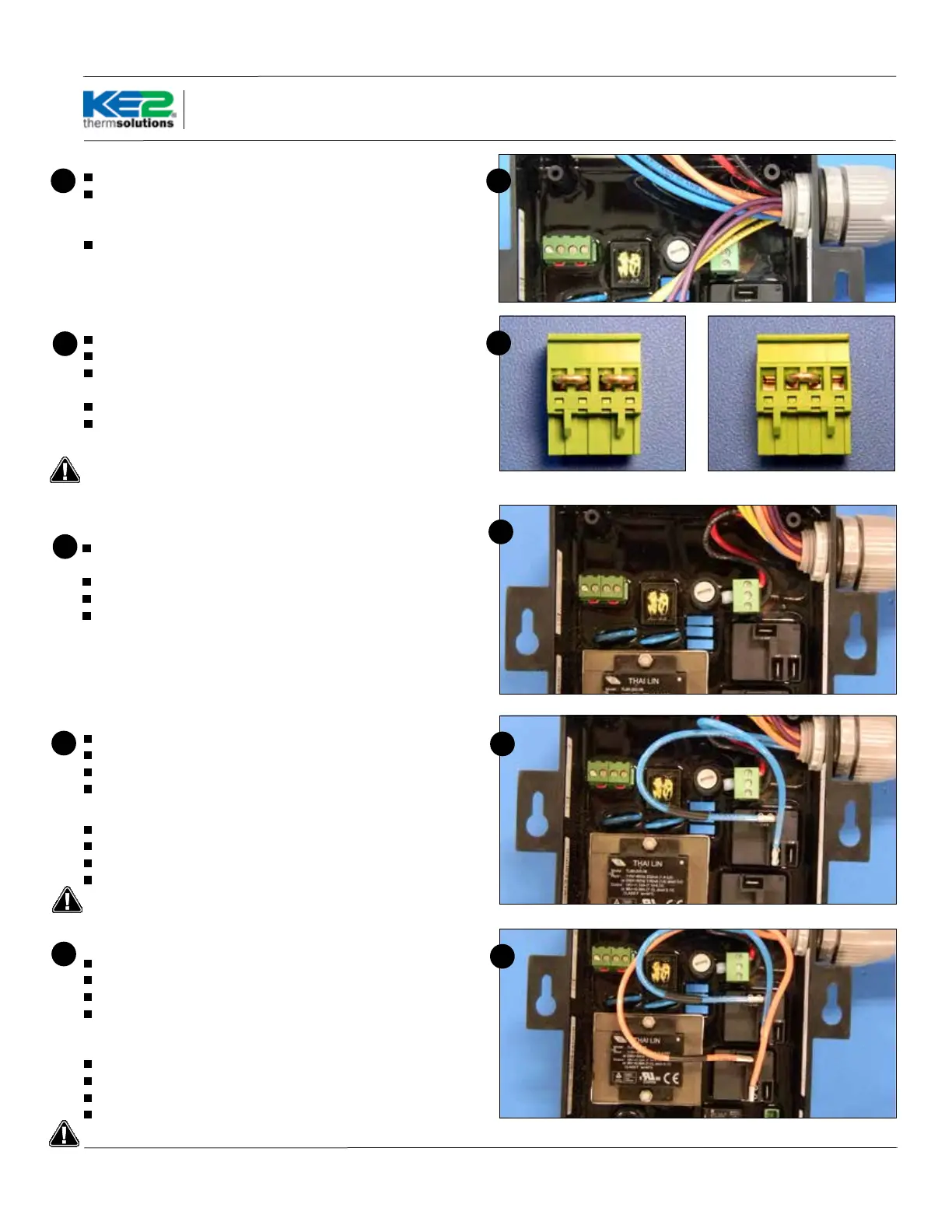
Preparing conduit
Feed the wires through the conduit.
The conduit connectors can be added at this time. Determine if a
straight or 90 degree connector is most appropriate for the installa-
tion, and attach to the conduit.
Securely connect one end of the conduit to the controller.
5 5
120V 208-240V
6
Controller Power
Strip the end of the wires used to provide power to the controller (If
using the KE2 Wire Harness the wires are pre-stripped)
Locate a 3 position terminal in the accessories kit.
Fasten to the 3 position pluggable connector*.
Plug into the board as indicated in Wiring Schematic.
*All terminal screws should be tightened to 5 ft-lbs.
7
7
Wiring the controller
Locate the second Voltage Jumper in the accessory kit.
It is a 4 position plug with 2 red jumper already installed.
Use the plug with 1 jumper for 208-240V power or the jumper with
2 jumpers for 120V power.
Power is not connected to Voltage selector, it is a selector only.
Power for the controller is connected to the Power In location us-
ing a 3 position connector.
Controller still illuminates display when 120V is applied with 208-
240V selected, however controller will not function properly.
6
Fan Relay
Strip the end of the 2 wires used for fan control.
Locate 2 female spade connectors in the accessories kit.
Crimp on the female spade connectors.
Plug the connectors to the COM and NO positions of the Fan Relay.
Fan Relay Using the KE2 Wire Harness
The blue wires are used for fan control.
They are blue with a black stripe, and the black with a blue stripe.
Plug the black with a blue stripe to the COM terminal.
Plug the blue with a black stripe to the NO position of the Fan Relay
Conrm combined fan motor load is not over 10 amps
8
8
Defrost (Heater) Relay
Strip the end of the 2 wires used for the defrost control.
Locate the remaining 2 female spade connectors in accessories kit.
Crimp on the female connectors.
Plug the connectors to COM and NO positions of the Defrost Relay.
Defrost (Heater) Relay Using the KE2 Wire Harness
The orange wires are used for the heater control.
Locate the orange with black stripe, and black with orange stripe.
Plug the black with orange stripe to the COM terminal.
Plug the orange w. black stripe to the NO position of Defrost Relay.
Conrm combined heater load is not over 20 amps.
9
9