© Copyright 2019 KE2 Therm Solutions, Inc., Washington, Missouri 63090
Q.3.65 June 2019
Page 2
KE2 Temp + Air Defrost (pn 20611)
For Medium Temperature Applications with Air Defrost
Condensed Quick Start Guide
KE2 Therm Solutions
12 Chamber Drive . Washington, MO 63090
1.888.337.3358 . www.ke2therm.com
4.50
6.68
2.30
2.79
0.20
Hole
1.09
Top View
End View
2.14
2.30
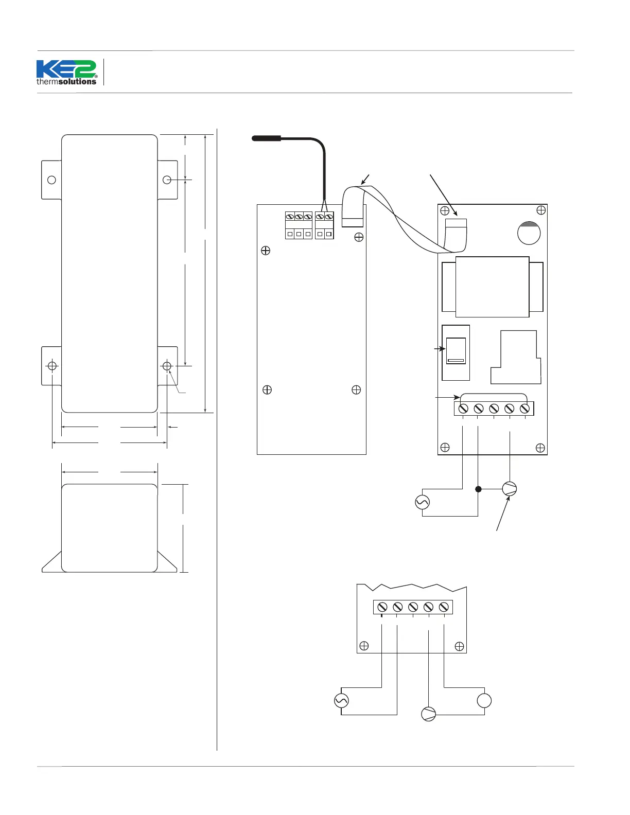
Dimensions - Inches
Wiring Diagram
Ribbon
Cable
Air Temp Sensor
120 (208 - 240)/1/60
CONTROLLER POWER SUPPLY
Neutral (L2)
NC
115/230
VAC
A B SH
RS 485
+ -
PWR CB
2 3 4 51
COM
NO
Relay
Put jumper
wire from
L1(terminal 1)
to COM
(terminal 5)
Observe proper orientation
of Ribbon Cable connection.
LLS (Liquid Line Solenoid) or
COMPRESSOR CONTACTOR
L1
Temp 1
Ribbon
Cable
Air Temp Sensor
120 (208 - 240)/1/60
CONTROLLER POWER SUPPLY
Neutral (L2)
NC
115/230
VAC
A B SH
RS 485
+ -
PWR CB
2 3 4 51
COM
NO
Relay
Observe proper orientation
of Ribbon Cable.
LLS (Liquid Line Solenoid) or
COMPRESSOR CONTACTOR
L1
Temp 1
+
_
LLS (Liquid Line Solenoid) or
COMPRESSOR CONTACTOR
POWER SUPPLY
Reference relay specifications
for Voltage and Current
Alternate Wiring Method
Select correct
voltage for
controller power:
115 or 230V
 Loading...