INSTALLATION INSTRUCTIONS R−410A Split System Air Conditioner
10 421 01 5100 01
REFRIGERANT CHARGE
Outdoor units are shipped with a refrigerant charge to
match a specific indoor coil and 15 feet of refrigerant line.
If shorter or longer refrigerant lines or a different indoor
coil are used, the charge will have to be adjusted.
For different line lengths, add or remove charge based on
0.6 ounces charge per foot of difference. For example, a
25 foot line set is 10 feet longer than the specified 15 feet.
Add 0.6 ounces charge for each of the extra 10 feet:
10 x 0.6 = 6.0 ounces additional charge
This outdoor unit is designed for use only with indoor coils
that utilize a hard shut−off TXV refrigerant metering de-
vice. With a hard shut−off indoor TXV, use the subcooling
method to make final charge adjustments:
1. Operate unit a minimum of 10 minutes before
checking charge.
NOTE: If outdoor unit has a 2−speed fan motor,
motor will operate in low speed when outdoor am-
bient temperature is below 82 °F. Pull one of the
yellow low voltage wires off the fan control and the
unit will default to high speed fan for servicing. Re-
connect wire after servicing.
2. Measure liquid service valve pressure by attaching
an accurate gauge to service port.
3. Measure liquid line temperature by attaching an
accurate thermistor type sensor or electronic ther-
mometer to liquid line near outdoor coil.
4. Refer to unit rating plate for required subcooling
temperature.
5. Refer to Figure 12. Find the required liquid line
temperature where the rating plate subcooling
temperature intersects measured liquid service
valve pressure.
6. If the measured liquid line temperature is higher
than the chart number, add refrigerant to lower the
measured temperature.
NOTE: When adding refrigerant, charge in liquid form,
using a flow restricting device, into the suction port.
If the measured liquid line temperature is lower than the
chart number, reclaim refrigerant to raise the measured
temperature.
Tolerance is 3 ° F.
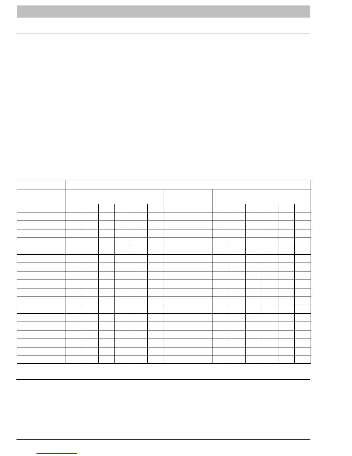
Figure 12 R−410A Required Liquid Line Temperature (°F)
Measured Liquid
Pressure (psig)
Rating Plate (required)
Subcooling Temperature (°F)
Measured Liquid
Pressure (psig)
Rating Plate (required)
Subcooling Temperature (°F)
6 8 10 12 14 16 6 8 10 12 14 16
189 60 58 56 54 52 50 326 96 94 92 90 88 86
195 62 60 58 56 54 52 335 98 96 94 92 90 88
202 64 62 60 58 56 54 345 100 98 96 94 92 90
208 66 64 62 60 58 56 354 102 100 98 96 94 92
215 68 66 64 62 60 58 364 104 102 100 98 96 94
222 70 68 66 64 62 60 374 106 104 102 100 98 96
229 72 70 68 66 64 62 384 108 106 104 102 100 98
236 74 72 70 68 66 64 395 110 108 106 104 102 100
243 76 74 72 70 68 66 406 112 110 108 106 104 102
251 78 76 74 72 70 68 416 114 112 110 108 106 104
259 80 78 76 74 72 70 427 116 114 112 110 108 106
266 82 80 78 76 74 72 439 118 116 114 112 110 108
274 84 82 80 78 76 74 450 120 118 116 114 112 110
283 86 84 82 80 78 76 462 122 120 118 116 114 112
291 88 86 84 82 80 78 474 124 122 120 118 116 114
299 90 88 86 84 82 80 486 126 124 122 120 118 116
308 92 90 88 86 84 82 499 128 126 124 122 120 118
317 94 92 90 88 86 84 511 130 128 126 124 122 120
SEQUENCE OF OPERATION
With power supplied to indoor and outdoor units, trans-
former is energized.
On a call for cooling, the thermostat makes circuits R−Y
and R−G. Circuit R−Y energizes contactor, starting out-
door fan motor and compressor. Circuit R−G energizes
indoor unit blower relay, starting indoor blower motor.
When thermostat is satisfied, its contacts open,
de−energizing contactor and blower relay. Compressor
and motors stop.
NOTE: If indoor unit is equipped with a time−delay relay
circuit, the blower runs an additional length of time to in-
crease system efficiency.