EasyManua.ls Logo

KeepRite DLCCHR - User Manual

Default Icon
82 pages
Print Icon
To Next Page IconTo Next Page
Loading...
Specifications subject to change without notice.
DLFCAB / DLCCAR / DLFCHB / DLCCHR
DLFDAB / DLCDAR / DLFDHB / DLCDHR
SERVICE MANUAL
High Wall Ductless Split System − Sizes 09 to 36
TABLE OF CONTENTS
PAGE
SAFETY CONSIDERATIONS 1.............................
INTRODUCTION 1.......................................
MODEL / SERIAL NUMBER NOMENCLATURES 2............
DIMENSIONS 3..........................................
CLEARANCES 5.........................................
WIRING 6...............................................
CONNECTION DIAGRAMS 7..............................
WIRING DIAGRAMS 8....................................
PCB PRINTED DIAGRAMS 18.............................
REFRIGERATION DIAGRAMS 31...........................
REFRIGERATION LINES 32................................
SYSTEM EVACUATION AND CHARGING 33.................
SEQUENCE OF OPERATION 34............................
TROUBLESHOOTING 36..................................
TROUBLESHOOTING FOR THE MAIN FUNCTION 41.........
DISASSEMBLY INSTRUCTIONS INDOOR UNIT 56...........
DISASSEMBLY INSTRUCTIONS OUTDOOR UNIT 62.........
APPENDIX 78...........................................
SAFETY CONSIDERATIONS
Installing, starting up, and servicing air−conditioning equipment can be
hazardous due to system pressures, electrical components, and
equipment location (roofs, elevated structures, etc.).
Only trained, qualified installers and service mechanics should install,
start−up, and service this equipment.
Untrained personnel can perform basic maintenance functions such as
cleaning coils. All other operations should be performed by trained
service personnel.
When working on the equipment, observe precautions in the literature and
on tags, stickers, and labels attached to the equipment.
Follow all safety codes. Wear safety glasses and work gloves. Keep a
quenching cloth and fire extinguisher nearby when brazing. Use care in
handling, rigging, and setting bulky equipment.
Read this manual thoroughly and follow all warnings or cautions included
in literature and attached to the unit. Consult local building codes and
National Electrical Code (NEC) for special requirements.
Recognize safety information. This is the safety−alert symbol
!
!
. When
you see this symbol on the unit and in instructions or manuals, be alert to
the potential for personal injury. Understand these signal words:
DANGER, WARNING, and CAUTION. These words are used with the
safety−alert symbol. DANGER identifies the most serious hazards which
will result in severe personal injury or death.
WARNING signifies hazards which could result in personal injury or
death. CAUTION is used to identify unsafe practices which may result in
minor personal injury or product and property damage. NOTE is used to
highlight suggestions which will result in enhanced installation, reliability,
or operation.
!
WARNING
ELECTRICAL SHOCK HAZARD
Failure to follow this warning could result in personal
injury or death.
Before installing, modifying, or servicing the system,
the main electrical disconnect switch must be in the OFF
position. There may be more than 1 disconnect switch.
Lock out and tag switch with a suitable warning label.
EXPLOSION HAZARD
Failure to follow this warning could
result in death, serious personal injury,
and/or property damage.
Never use air or gases containing
oxygen for leak testing or operating
refrigerant compressors. Pressurized
mixtures of air or gases containing
oxygen can lead to an explosion.
!
WARNING
CAUTION
!
EQUIPMENT DAMAGE HAZARD
Failure to follow this caution may result in equipment
damage or improper operation.
Do not bury more than 36 in. (914 mm) of refrigerant pipe
in the ground. If any section of pipe is buried, there must be
a 6 in. (152 mm) vertical rise to the valve connections on
the outdoor units. If more than the recommended length is
buried, refrigerant may migrate to the cooler buried section
during extended periods of system shutdown. This causes
refrigerant slugging and could possibly damage the
compressor at start−up.
INTRODUCTION
This service manual provides the necessary information to service,
repair, and maintain the ductless family cooling only and heat pumps.
Section 2 of this manual is an appendix with data required to perform
troubleshooting. Use the Table of Contents to locate a desired topic.

Table of Contents

Other manuals for KeepRite DLCCHR

Question and Answer IconNeed help?

Do you have a question about the KeepRite DLCCHR and is the answer not in the manual?

Summary

Safety Considerations

Electrical Shock Hazard Warning

Failure to follow this warning could result in personal injury or death.

Explosion Hazard Warning

Failure to follow this warning could result in death, serious personal injury, and/or property damage.

Equipment Damage Hazard Caution

Failure to follow this caution may result in equipment damage or improper operation.

Introduction and Overview

Service Manual Scope

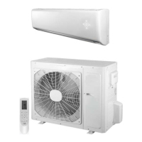
Provides information for servicing, repairing, and maintaining cooling and heat pump units.

Model and Serial Number Nomenclature

Indoor Unit Model Designation

Details the coding system for indoor unit model numbers.

Outdoor Unit Model Designation

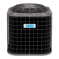
Details the coding system for outdoor unit model numbers.

Clearances for Installation

Indoor Unit Clearance Requirements

Specifies minimum clearance distances for indoor unit installation.

Outdoor Unit Clearance Requirements

Specifies minimum clearance distances for outdoor unit installation.

Wiring Specifications

Wiring Installation Cautions

Cautions regarding wiring installation, compliance with codes, and wire types.

Electrical Data Tables

Provides running current, MCA, and MOPA for different system sizes and voltages.

Connection Diagrams

115 V Connection Diagram (9 K & 12 K Units)

Wiring diagram for 9K and 12K units operating at 115V.

208;230 V Connection Diagram (9 K & 12 K Units)

Wiring diagram for 9K and 12K units operating at 208/230V.

208;230 V Connection Diagram (18 K - 36 K Units)

Wiring diagram for 18K to 36K units operating at 208/230V.

Indoor Unit Wiring Diagrams

DLFCAB; DLFCHB Wiring (Sizes 09-12)

Wiring diagram for DLFCAB/DLFCHB indoor units, sizes 09-12.

Indoor Unit Wiring Diagrams (Continued)

DLFCAB;DLFCHB Wiring (Sizes 18-24)

Wiring diagram for DLFCAB/DLFCHB indoor units, sizes 18-24.

DLFCAB;DLFCHB Wiring (Sizes 30-36)

Wiring diagram for DLFCAB/DLFCHB indoor units, sizes 30-36.

Outdoor Unit Wiring Diagrams (DLCCAR; DLCCHR)

DLCCAR;DLCCHR Wiring (Sizes 09-12, 115 V)

Wiring diagram for DLCCAR/DLCCHR outdoor units, sizes 09-12 (115V).

DLCCAR;DLCCHR Wiring (Sizes 09-12, 208;230 V)

Wiring diagram for DLCCAR/DLCCHR outdoor units, sizes 09-12 (208/230V).

Outdoor Unit Wiring Diagrams (DLCCAR; DLCCHR) (Continued)

DLCCAR;DLCCHR Wiring (Size 18, 208;230 V)

Wiring diagram for DLCCAR/DLCCHR outdoor unit, size 18 (208/230V).

DLCCAR;DLCCHR Wiring (Sizes 30-36, 208;230 V)

Wiring diagram for DLCCAR/DLCCHR outdoor units, sizes 30-36 (208/230V).

DLCCAR;DLCCHR Wiring (Size 24, 208;230 V)

Wiring diagram for DLCCAR/DLCCHR outdoor unit, size 24 (208/230V).

DLFDAB;DLFDHB Indoor Unit Wiring (Sizes 09-12, 115 V)

Wiring diagram for DLFDAB/DLFDHB indoor units, sizes 09-12 (115V).

Indoor Unit Wiring Diagrams (DLFDAB; DLFDHB) (Continued)

DLFDAB;DLFDHB Wiring (Sizes 09-24, 208;230 V)

Wiring diagram for DLFDAB/DLFDHB indoor units, sizes 09-24 (208/230V).

DLFDAB;DLFDHB Wiring (Sizes 30-36, 208;230 V)

Wiring diagram for DLFDAB/DLFDHB indoor units, sizes 30-36 (208/230V).

Outdoor Unit Wiring Diagrams (DLCD)

DLCDAR Wiring (Sizes 09-12, 115 V)

Wiring diagram for DLCDAR outdoor units, sizes 09-12 (115V).

DLCDAR Wiring (Sizes 09-12, 208-230 V)

Wiring diagram for DLCDAR outdoor units, sizes 09-12 (208-230V).

Outdoor Unit Wiring Diagrams (DLCD) (Continued)

DLCDAR Wiring (Sizes 18-24, 208-230 V)

Wiring diagram for DLCDAR outdoor units, sizes 18-24 (208-230V).

DLCDHR Wiring (Sizes 09-12, 208;230 V)

Wiring diagram for DLCDHR outdoor units, sizes 09-12 (208/230V).

DLCDHR Wiring (Sizes 09-12, 115 V)

Wiring diagram for DLCDHR outdoor units, sizes 09-12 (115V).

DLCDHR Wiring (Sizes 18-24, 208;230 V)

Wiring diagram for DLCDHR outdoor units, sizes 18-24 (208/230V).

Refrigeration Diagrams

Refrigerant Lines and Charging

General Refrigerant Line Sizing Guidelines

Guidelines for sizing refrigerant lines and charge adjustments for longer runs.

System Evacuation and Charging

Unit Damage Hazard Caution During Evacuation

Warning regarding proper vacuum pump usage to prevent unit damage.

System Vacuum and Charge Procedure

Step-by-step instructions for evacuating the system using a vacuum pump.

Modes and Operation Sequences

Vacuum Pumping and Leak Detection Process

Outlines the procedure for vacuum pumping and leak detection.

Advanced Operation Modes

Leakage Detection Methods

Methods for detecting refrigerant leakage using detector or soap water.

Troubleshooting Guide

Required Tools for Diagnosis

Lists essential tools needed for diagnosing unit problems.

Recommended Troubleshooting Steps

Outlines systematic steps for troubleshooting and checking diagnostic codes.

Troubleshooting - Malfunction Codes

Table 23 - Primary Malfunction Indicators and Causes

Lists malfunction codes, LED indicators, AC status, and possible causes.

Troubleshooting - Malfunction Codes (Continued)

Table 23 - Primary Malfunction Indicators and Causes (Continued)

Continues listing malfunction codes, LED indicators, AC status, and possible causes.

Troubleshooting Main Malfunctions (Indoor Unit)

1. Malfunction of Temperature Sensor F1, F2

Troubleshooting flowchart for temperature sensor malfunctions F1 and F2.

2. Malfunction of Blocked Protection of IDU Fan Motor H6

Troubleshooting flowchart for IDU fan motor blocked protection (H6).

3. Malfunction of Protection of Jumper Cap C5

Troubleshooting flowchart for jumper cap protection malfunction (C5).

4. Malfunction of Over Current Protection E5

Troubleshooting flowchart for over current protection malfunction (E5).

5. Communication Malfunction E6

Troubleshooting flowchart for communication malfunction (E6).

Troubleshooting Outdoor Unit (09 K;12 K)

1. Capacity Charging Malfunction

Troubleshooting for capacity charging malfunction in outdoor units.

Troubleshooting Outdoor Unit Issues

2. Reactor and PFC Capacitor Check

Fault diagnosis process for reactor and PFC capacitor issues.

3. Communication Malfunction Diagnosis

Fault diagnosis process for communication malfunctions.

4. High Temperature and Overload Protection (E8)

Troubleshooting flowchart for high temperature and overload protection.

5. Start-Up Failure (LC)

Troubleshooting flowchart for start-up failure (LC).

6. Overload and High Discharge Temperature Malfunction

Troubleshooting flowchart for overload and high discharge temp malfunctions.

Troubleshooting Common Issues

Troubleshooting Common Issues (Continued)

11. Communication Malfunction (E6)

Troubleshooting flowchart for communication malfunction (E6).

Troubleshooting - General Issues

Troubleshooting - Common Failures

Disassembly Instructions - Outdoor Unit (9-12)

Warning: Refrigerant Discharge & Power Off

Warning to discharge refrigerant and turn off power before removal.

KeepRite DLCCHR Specifications

General IconGeneral
BrandKeepRite
ModelDLCCHR
CategoryAir Conditioner
LanguageEnglish

Related product manuals