8 328 080000 01
Specifications subject to change without notice.
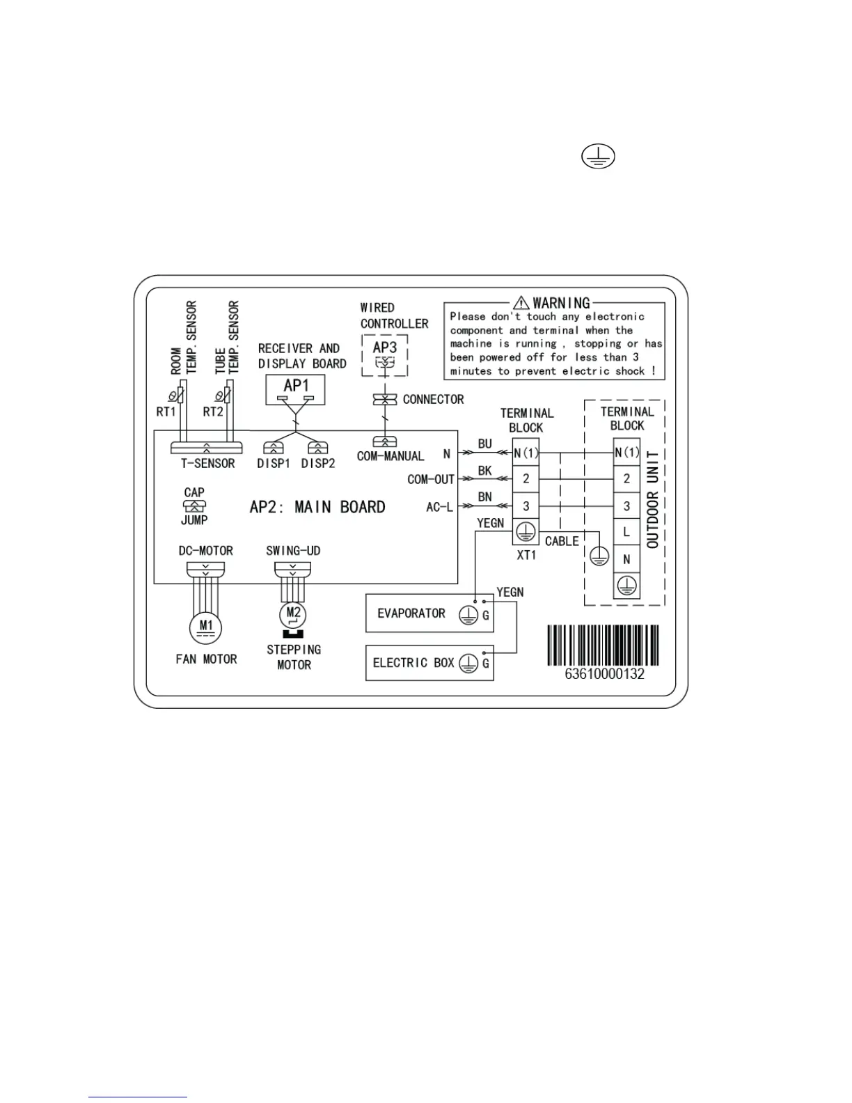
WIRING DIAGRAMS
Table 10—WIRING DIAGRAMS
SYMBOL
SYMBOL COLOR SYMBOL SYMBOL COLOR SYMBOL NAME
WH White GN Green CAP Jumper Cap
YE Yellow BN Brown COMP Compressor
RD Red BU Blue Grounding wire
YEGN Yellow/Green BK Black / /
VT Violet OG Orange / /
NOTE: Jumper cap is used to determine the fan speed and the swing angle of the horizontal louver of this model.
WIRING DIAGRAM − INDOOR UNIT − DLFCAB / DLFCHB
Fig. 9 - Indoor Unit Sizes 09 − 12 (115V − 208/230V)