2-10
The auto rate may be varied from 50msec to 999.9sec. The
power up default value of the auto rate is 50msec. The one
second rate used in this example is used just for learning
purposes. In another situation, the rate could be programmed
much faster or slower. Once the desired value is reached,
deactivating the AUTO button stops the auto increment/
decrement action.
The auto mode is a convenient function that allows for precise
currents to be stepped. This could be used to test
semiconductors at several different current values, The only
difference between this example and the example of stepping
the current is the actual value of current; and the OUTPUT
button is activated.
The auto mode could also be used to decrement the current
value. After step 11, press DIGIT,DIGIT,DIGIT,AUTO,DECR.
Then observe the display decrease the value of current by
1mA every second. Stop the decrement at the 1mA level,
otherwise the Model 224 will display the ERR (error) message
and remain at the value of 00.00-3A. The error message is
displayed because the instrument was on the 100mA range
and then it was instructed to auto increment outside of that
range. Refer to the Auto Mode Notes in this example.
Example 6 Triggering:
The Model 224 may be triggered to
increment or decrement the selected digit in two ways:
1. With the front panel TRIG button activated, apply a trigger
pulse (TTL level-negative going) to the rear panel
EXTERNAL TRIGGER INPUT. Refer to Figure 2-5 for
pulse specifications.
2. With commands given over the IEEE bus. This action
requires that the Model 2243 IEEE-488 interface option
be installed.
External Trigger Notes:
1. The front panel TRIG button is used to control the rear
panel EXTERNAL TRIGGER INPUT connector. Pressing
this button once enables the external trigger and turns on
the TRIG LED. Pressing the button again disables the
external trigger operation and turns off the TRIG LED.
2. The TRIG and the AUTO functions are mutually exclusive.
3. The DIGIT button must be activated before the TRIG but-
ton is activated.
4. INCR or DECR must be selected after TRIG is activated.
5. While in the TRIG mode, pressing the TRIG button stops
the operation. Pressing TRIG once more resumes the
operation from where it was stopped.
6. The external trigger output is controlled by the TRIG but-
ton. When the selected digit is incremented or decre-
mented a pulse (TTL level-negative going) appears at the
EXTERNAL TRIGGER OUTPUT connector. The specifi-
cations of the pulse are shown in Figure 2-5.
7. While the auto or trig modes are activated, the four but-
tons in the DISPLAY group (SOURCE, V-LIMIT, I-LIMIT
and TIME) are locked out.
This example covers the front panel TRIG button, the external
trigger input and output connectors. The external trigger oper-
ates in conjunction with the front panel TRIG button. That is,
the front panel TRIG button must be activated before the
Model 224 will accept an external trigger stimulus.
To illustrate the front panel TRIG button and the external trig-
ger input use the following procedure:
1. Connect the external trigger source to the rear panel BNC
EXTERNAL TRIGGER INPUT connector.
2. Press the SOURCE button to activate the source function.
3. Press the DIGIT button to select the desired digit that is to
be modified.
4. Press the front panel TRIG button to activate the trigger
mode.
5. Press INCREMENT or DECREMENT.
6. To trigger the instrument, apply a pulse to the EXTERNAL
TRIGGER INPUT. The pulse must conform to the specifi-
cations shown in Figure 2-5.
7. With just one pulse applied the Model 224 modifies the
selected digit by one count.
8. Press OPERATE to output the current.
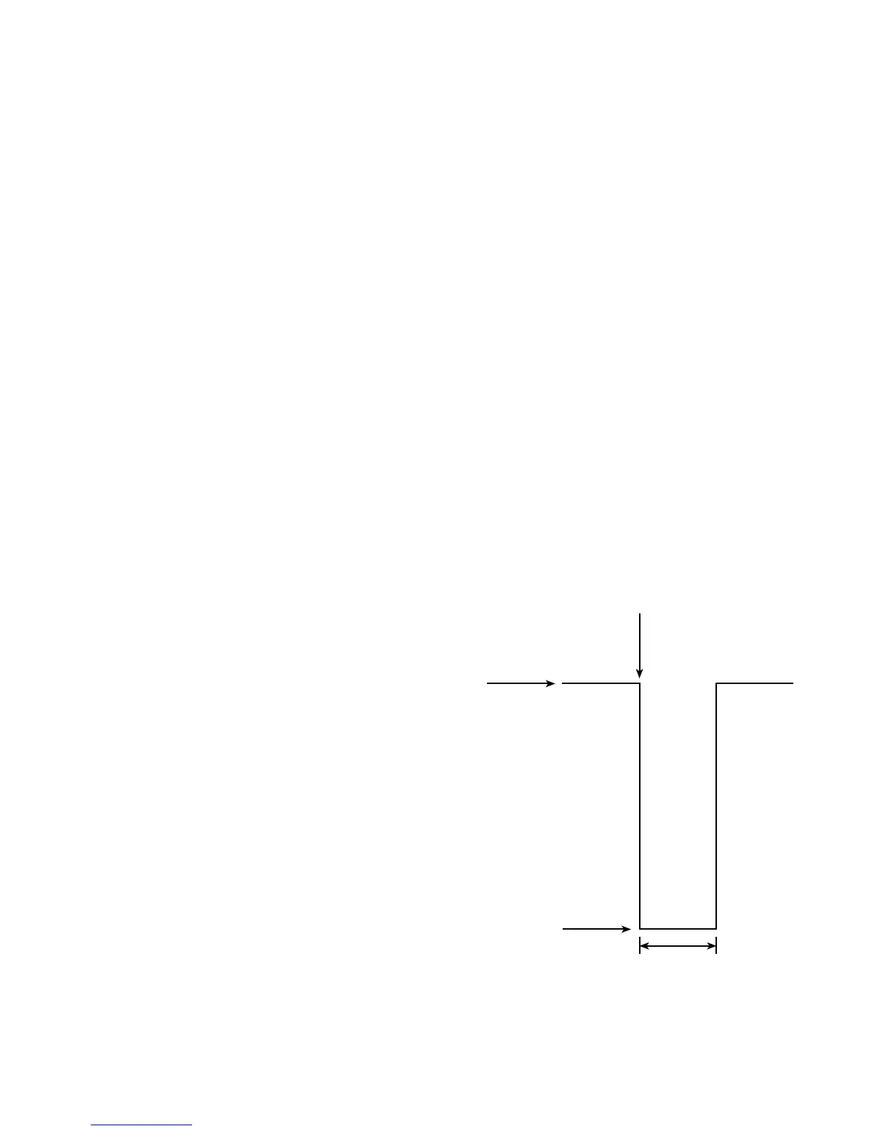
Figure 2-5. External Input and Output Trigger Pulse
Specifications
TTL
HIGH
TTL
LOW
TRIGGER ON
NEGATIVE
GOING
PULSE
10µSEC
MINIMUM
CAUTION: DO NOT EXCEED NORMAL TTL LEVELS