Leakage Current and Insulation Resistance
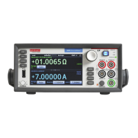
Measurements Using the Model 2450
SourceMeter
®
SMU Instrument
Introduction
To measure the leakage current or insulation resistance of a
device, you need to apply a fixed voltage to the device and
measure the resulting current. Depending on the device under
test, the measured current is typically very small, usually less
than 10nA.
This application consists of two examples that demonstrate:
• How to use the Model 2450 to perform leakage current
measurements on a capacitor
• How to use the Model 2450 to measure insulation resistance
between the two conductors of a coaxial cable
The only difference between these two application examples
is that when you measure leakage current, the results are
returned in units of amperes. When you measure insulation
resistance, the results are returned in units of ohms.
The leakage current application applies the voltage for a
specified period because the device needs time to charge. In
some cases, the resulting current is measured the entire time the
device is biased. In other cases, only one reading is made at the
end of the soak period.
The following topics describe how to do these applications
from the front panel. They also show how to do them using a
remote interface with SCPI commands or Test Script Processor
(TSP
®
) commands.
Equipment required
• One Model 2450 Interactive SourceMeter® instrument
• Two triaxial cables
• One capacitor for the leakage current application
• One coaxial cable or other device for the insulation resistance
application
• One ethernet, GPIB, or USB cable for the TSP and SCPI
remote command examples
Set up remote communications
You can run this application from the front panel or any of the
supported communication interfaces for the instrument (GPIB,
USB, or ethernet).
The following figure shows the rear-panel connection
locations for the remote communication interfaces.
Figure 1. Model 2450 remote interface connections.
Device connections
Depending on the device under test (DUT), the current
measurement is typically very small, usually <10nA. Measuring
leakage current and insulation resistance involves measuring very
small values. To get more accurate readings, connect the DUT to
the Model 2450 rear panel with low-noise triaxial cables.
Connect the DUT between the FORCE HI and FORCE LO
terminals of the Model 2450.
Figure 2
shows schematic diagrams. One shows measuring
the leakage current of a capacitor. The other shows measuring
the insulator resistance between two conductors of a
coaxial cable.
Figure 2. Connection schematics for the capacitor leakage and insulation
resistance tests.
The following figures show the rear-terminal connections to
the device under test (DUT) for these applications. If capacitor
leakage measurements are noisy, you may need to use the high
capacitance mode or add a low leakage forward-biased diode in
series with the capacitor.
Number 3262
Application Note
Se ries




 Loading...