2600S-901-01 Rev. C / January 2008 Return to Section Topics 3-3
Series 2600 System SourceMeter® Instruments Reference Manual Section 3: DUT Test Connections
Figure 3-1
2602/2612 input/output connectors
S
HI
CHANNEL B
GGGG S
LO
HI LO
S
HI
CHANNEL A
G
GGG
S
LO
HI
LO
Channel B Channel A
HI = Input/Output HI
S HI = Sense HI
G = Guard
S LO = Sense LO
LO = Input/Output LO
Captive screw (2 per terminal block)
Each terminal block uses two captive
screws to secure it to the rear panel.
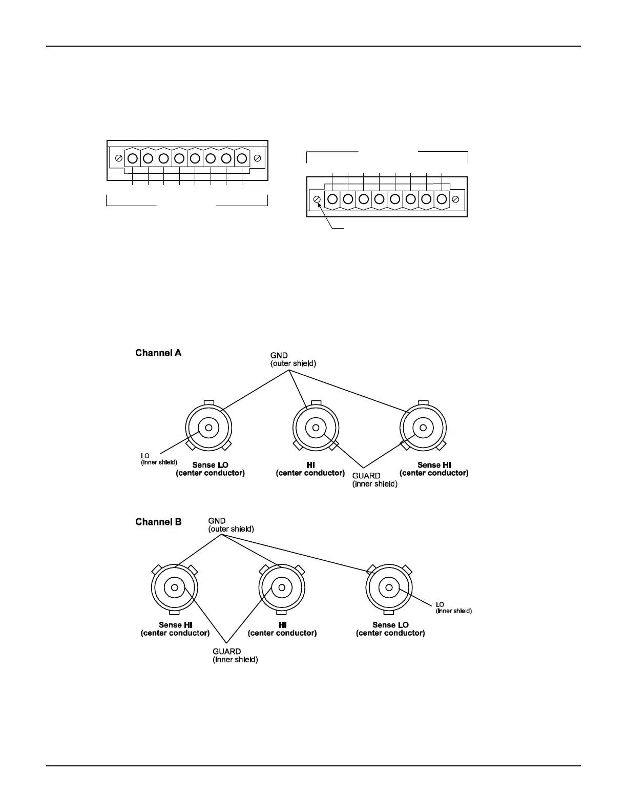
Figure 3-2
Model 2636 input/output connectors
Input/output LO and chassis ground
As shown in Figure 3-3, SMU input/output LOs are available at the rear panel terminal blocks.
Input/output LOs are not connected between channels and are electrically isolated from chassis
ground.
 Loading...


